background image

TEMA TELECOMUNICAZIONI SRL


Doorphone AA-514 

MAS-AA514-REV03EN 


 Page 53 of 56 

 
Triple system, composed of three elements, base system plus two expansion module 
 
If it is used a AA-514 system with two expansion module, for example one AA-516K + AA-516R, please follow the 
next indications. 
  
Provide to recess the plastic back box at the right distance  between them. To facilitate the installation, with each 
back  box  is  provided  a  particular  tube  cable  that  allows  to  horizzontaly  hook  the  metallic  shells  side  by  side,  in 
order  to  keep  them  in  the  right  position  to  be  recessed  in  the  wall.  So  the  tube  cable  held  the  function  to  made 
possible  the  passage  of  the  cables  between  one  back  box  and  the  other  without  having  to  run  other  pieces  of 
corrugated tube. 


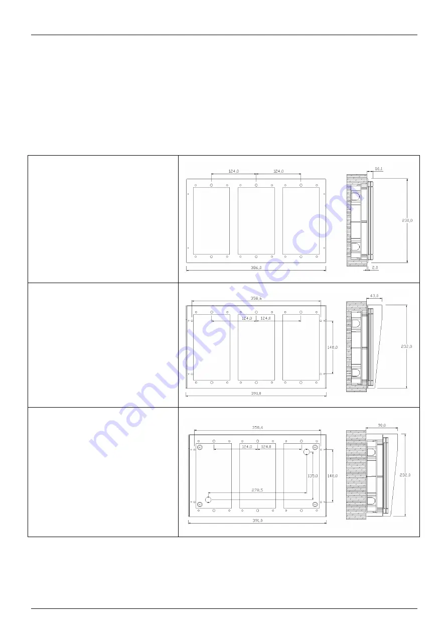
To  facilitate  the  finishing  and  the 
system/wall junction there is the possibility 
to  use  the  wall  cover  metal  frame 
accessory  called  AA-517-C3  with  3 
positions side by side. 
 
If  the  accessory  is  not  provided,  the  front 
panel  of  the  systems  with  its  frame  will 
simply  go  directly  to  the  wall,  fixed  to  the 
metallic recessed back box. 


Even  the  shield  accessory  AA-517-T3 
(cover  for  protection  of  3  systems)  is 
designed to be put in place on 3 back box  
previously  walled  with  the  aid  of  the 
particolar tube cable previously described. 


When  is  used  the  AA-517-S3  accessory 
(single  full  box  for  3  systems),  it  is  not 
necessary  to  recess  the  plastic  back  box 
to  the  wall.  In  fact  all  the  system  is  fixed 
on  the  wall.  First  is  placed  the  box,  then 
the rest of the system. 


Summary of Contents for AA-502

Page 1: ...ble for any damage caused by the use of materials that they have not supplied 2 The device has been carefully manufactured and tested In any case the product is not recommended for use in situations in which incorrect operating may result in damage to persons and or property 3 We recommend that you carefully read all this manual before starting to use the device 4 Do not expose the device to sunli...

Page 2: ...h the essential requirements and other relevant requirements of the R TTE Directive 1999 5 EC 2006 95 EC 2004 108 EC The product is in conformity with the followings standards and or other normative documents HEALT SAFETY EN 60950 1 2006 A11 2009 A1 2010 A12 2011 EMC EN 55022 2010 EN 55024 2010 EN 61000 3 2 2006 EN 61000 3 3 2008 TERMINALE DI ES 203 021 Access and Terminals AT Harmonized basic TEL...

Page 3: ...ling techniques Specific treatment for WEEE is indispensable in order to avoid the dispersion of pollutants and other hazardous substances into the waste stream while recycling leads to reduction of disposal of waste and the negative impacts on environment and human health That is priority is given to reuse of WEEE in its components subassemblies and consumables As the final holder the user has an...

Page 4: ...516R 27 8 3 4 CONNECTION OF THE BASE SYSTEM AA 514C WITH CAMERA 28 8 4 DESCRIPTION OF THE TERMINAL BLOCKS OF RELAYS 29 8 4 1 SOLID STATE RELAYS AND ELECTROMECHANICAL RELAYS 29 8 5 DESCRIPTION AND EXAMPLES OF OPERATION MODES WITH THE INTERNAL RELAYS CONNECTIONS 30 8 5 1 CASE 1 DRIVE TWO ELECTRIC LOCKS WITH SYSTEM POWERED WITH EXTERNAL POWER SUPPLY 30 8 5 2 CASE 2 DRIVE OF TWO ELECTRIC LOCKS WITH SY...

Page 5: ...ersion with electromechanical relays and amplified audio is the model AA 514A The base system in version with solid state relays is the model AA 514H The base system in version with solid state relays and amplified audio is the model AA 514HA The systems listed above are available with built in analog color camera in the versions AA 514xC The base system is available with 4 buttons There is an exp...

Page 6: ...each relay to allow to access to the company directly from the doorphone without the intervention of the operator eg useful to service personnel or external assistance which for work reasons frequently comes out and return back in company Up to 200 programmable access codes to allow to access to the company directly from the doorphone without the intervention of the operator option available only ...

Page 7: ... An AA 516P module 8 push buttons Cable for connection to the base unit AA 514 A special key for the front panel screws Two plastic sliding tabs for frontal screws protection A set of die cut labels with extractor for label holders The AA 516K expansion consists of the parts included in the following list An AA 516K module full numeric keypad Cable for connection to the base unit AA 514 A special ...

Page 8: ...tem with camera the main features that characterize it and the required needed configuration AA 514C AA 514AC AA 514HC AA 514HAC Amplified Audio Yes Yes Doorphone and conversation Yes Yes Yes Yes Relay drive EM EM SS SS Fixed Backlight Automatic Backlight Yes Yes Yes Yes Yes Yes Anti condensation internal heating Yes Yes Yes Yes Camera support Yes Yes Yes Yes SOFT ON front camera area lighting Yes...

Page 9: ...Expansion AA 516KA Expansion AA 516KB Expansion AA 516KC Expansion AA 516R Numbers of buttons 8 Telephone Keypad Yes Door opening codes Yes Yes Button matching to the phone number Yes Yes keys from 1 to 9 Direct number dialing Yes Speed dial Yes Possibility of filter prefix digits Yes Backlighting Yes Yes legend keyboard only AA 516KC Yes Label holder Yes buttons Yes front area Additional front ar...

Page 10: ...ate relay circuits 12V Difference of potential between 3 power sources that can be connected to AA 514 system relay 1 relay2 1500V Insertion type terminals for relays and other Possibility to use cables up to 1 5mm2 or AWG16 Material of the container Corrosion resistant aluminium 9006 1 T6 6060 T6 Buttons body in Mackrolon Polycarbonate UL94 V2 ABS Novodur heads Mounting type Flush mounting wall m...

Page 11: ... Current when line is released 250µA Line Impedance 8000Ω 1KHz Audio bandwidth 300 3400Hz Impedance during RING 40000Ω 200 4300Hz 5000Ω 12 16KHz RING sensibility 10Vrms 25 50Hz Line voltage current characteristic 8Vdc 20mA Minimum operating current line 24Vdc 7 5Vdc 15mA Line imp 1200Ω line 48Vdc 7 6Vdc 18mA Line imp 1200Ω Impedance with taken line According to ETSI ES 203 021 Return loss Accordin...

Page 12: ...ck during the conversation The characteristics and the loudspeaker level and microphone adjustments of AA 514 are made at the factory and normally allows to overcome these situations without having to take other special precautions Finally there is the possibility to enable the noise reduction to improve the calls audio quality AA 514 allows to manage the two built in electromechanical relays in t...

Page 13: ...umber 314 This service is also found useful to mask the true extension number of the person to contact In addition this field or service may be used to avoid to make calls directly from the system when equipped with a AA 516K keypad engaging the external lines of the connected PBX In fact if a visitor will try to dial 02123456 the system will call 302 123456 preventing the external call The direct...

Page 14: ...escriptions of the operating modes listed below are valid only for the numbers associated with the Speed Dial service 6 1 DAY NIGHT Mode In the Day mode will be called the number associated with the corresponding pressed button associated in the parameters 110 111 112 113 In Night mode will be called the number associated with the corresponding pressed button parameters 114 115 116 117 At the pres...

Page 15: ...he number associated with the Night mode button then Day and then the third number This operating mode is particularly useful when you want to get the best chance to contact one of the operators by the visitor temporary job sites other 6 4 Additional features of the keypad expansion If the expansion module AA 516K is installed the visitor can make a call simply by dialing the desired number if kno...

Page 16: ...ial is 15 digits Enabling this new function it is NOT possible to use the Day Night Cycling operating modes of AA 514 the Doorphone will be in fact always considered exclusively set up in Day mode regardless of the related programmed parameters The audio messages playable from AA 514 last up to 7 seconds each for a total of 14 seconds compared to 16 seconds of the previous versions Enabling the ne...

Page 17: ...ll activate the associated relay regardless of the AA 514 day night mode set To enable this service it is necessary to program the proper parameters from 3000 to 3199 please refer to the parameter table for the correct values 6 8 Calls generated by AA 514 These are the calls that the system generates on the line triggered by the pressure of the button by a visitor by the previously described ways ...

Page 18: ... Please note that in all cases the functions of time out reorder tone silence disconnection are enabled and also the DTMF commands that the operator can normally send to AA 514 When the system is set up in this way it is in fact not possible to establish a bi directional conversation 6 10 Additional features of the built in camera and the dedicated front lighting The systems equipped with built in...

Page 19: ...eter 119 close call 2 Activate the door opener contact of the relay 2 Used to activate the second relay during communication it is a code from 1 to 4 digits default 2 Defined in parameter 141 Warning the function is also regulated by the parameter 144 that should be set to 0 to allow the operator for the function described here 3 Set the DAY mode Sets AA 514 so that the pressure of the call button...

Page 20: ...stand by the Led is off When receiving a call the Led flashes according to the ring frequency with the system in conversation the Led follows the level of voice and also indicates the presence or absence of dialing tones In the second mode of operation that can be set using the parameter 156 when the system is busy the Led lights steadily and remains lit for the duration of the conversation Below ...

Page 21: ...insert between frame and box then flush with the wall a special accessory called AA 517 This one improves the aesthetics of the system in the case the wall is made of a material that can not be cut or not match to the flush plastic box Moreover this flat frame applied between the wall and the aluminum frame of the system once screwed provides to help to seal the front wall junction Keep in mind to...

Page 22: ... built in gasket system that if installed between AA 517 C and the system seal any gaps that may be left between the wall and the front of the system For installation of this accessory see the steps on the previous page The flushed plastic box is the anchoring element of the plain frame and of the front of the system when closed with the special front screws RAIN SHIELD cover Accessory option AA 5...

Page 23: ...fitted to the wall or on the surface scheduled installation Open the holes C that you want to use for securing the SM box to the wall with the help of a tool that pushes away the preprinted material that covers every single hole to be released Also open the D holes that you want to use for the passage of cables in the same manner Place the metal box directly on the wall to mark the holes to be mad...

Page 24: ...nsparent field useful to give informations for visitors The model AA 516R specially designed possesses even two areas Because the informations to be presented can be variables for text and graphical form TEMA has provided a practical system of information badges customizing in a text file can be edited directly by the person that install the systems or directly by the end user In the supplied CD R...

Page 25: ...ment FC polarized connector for connection of the expansion cable to the AA 516P or AA 516K systems For details of the connection of the signals on terminal blocks TB1 and TB3 for the relays see section 8 4 Once that the bottom rear plastic box of the system is arranged in the wall take the front panel with the electronic board insert the two transparent plastic pins present on frame into the appr...

Page 26: ...ions do not remove the system board from the front panel but just remove the insertion connectors H jumper for internal heating circuit L jumper for backlighting circuit FC polarized connector for connection of the expansion cable from the AA 514 system TB3 terminals block for the Day Night service keys backlighting when controlled by the relay 2 of the AA 514 base system and redistribution of the...

Page 27: ...n connectors H jumper for internal heating circuit L jumper for backlighting circuit TBE2 terminals for connection of an additional power source for the backlighting of this expansion unit and any others following the power supply capacity TBE3 terminals block for the Day Night service keys backlighting when controlled by the relay 2 of the AA 514 base system and redistribution of the command to t...

Page 28: ...t accidental contacts being electrically insulated from its metal parts with the use of a special protective thermoformed cover Immediately near the operator monitor must be connected on the same pair another balun also supplied with the unit who will present the video signal to the monitor on a male BNC connector which can further be linked to other adapters BNC to RCA etc according to the type o...

Page 29: ...rtainly independent of the number of drives compared to electromechanical component The two types of relays when used in the circuits of AA 514 allow to get the use of the system in different conditions as described below The systems equipped with electromechanical relays have the following characteristics to operate the relays is necessary that the system is powered with external power adapter AA...

Page 30: ...note that is needed to connect the terminal blocks TB1 TB3 TB4 as shown the power supply is unique and common The telephone line must be connected on the TB2 terminal block The connections to be made during the stages of installation are shown in dashed lines In this example the correct values of the parameters involved in the management of the relays could be parameter 138 0 the relay1 is activat...

Page 31: ...upply of AA 514H that feeds itself from the telephone line connected to the terminal block TB2 The connections to be made during the stages of installation are shown in dashed lines This mode of operation can not be achieved with systems equipped with electromechanical relays In this example the correct values of the parameters involved in the management of the relays could be parameter 138 0 the ...

Page 32: ...hem Note the separate connections on the blocks TB1 TB3 and TB4 The telephone line must be connected on the TB2 terminal block The connections to be made during the stages of installation are shown in dashed lines Using the possibilities of connection of the power supplies and loads offered by AA 514 it is possible to get a great flexibility in driving loads with different electrical characteristi...

Page 33: ...ty of bringing the external power supply to the terminal block TB1 3 4 and to redistribute it to power to the system from the terminal TB1 1 2 to the terminal TB4 1 2 allows to make all the necessary connections without ever being forced to insert two wires into a single terminal block a practice to be avoided in electrical systems where and when possible In this example the correct values of the ...

Page 34: ...on of the relay1 that a person is entered in the warehouse Automatically every time a gate is opened is carried out an alert for the warehouse employees TB3 is designed for use only contact relay2 the system is powered on TB4 on TB1 connects the electric lock and on TB2 the telephone line In this example the correct values of the parameters involved in the management of the relays could be paramet...

Page 35: ...ystem is correctly placed in Night mode For this service is needed to bring the same system power supply from TB1 to TB4 and then to establish a connection also between TB5 and TB3 as per drawing The telephone line must be connected on the TB2 terminal block Caution with the system set up in this mode the jumper L on the board must be left open In this example the correct values of the parameters ...

Page 36: ...wer the only base system with AL 39AL on TB4 Connect the base system with the keyboard expansion using the FC flat cable supplied with the expansion module Then connect the terminal TB5 of the base AA 514 with the terminal TBE3 of the expansion AA 516R see next page for details AA 514 AA 516K three AA 516R modules Keep in mind the power consumption of all modules that are going to be connected wit...

Page 37: ...N Page 37 of 56 AA 514 AA 516R AA 516R Power supply 12Vac AA 516R AA 516R AA 516R Power supply 12Vac 8 5 8 Connecting AA 516R modules in cascade starting from a AA 514 base module 8 5 9 Connecting AA 516R modules in cascade starting from a AA 516R powered module ...

Page 38: ...instructions Call the number where AA 514 is connected Wait for the AA 514 answer Insert 3 time star key Wait for a long confirmation beep Insert programming password code default 1234 Wait for a long confirmation beep Insert 110 parameter 110 Wait for a long confirmation beep Insert 220 parameter value Wait for a short confirmation beep Insert confirm data and store it Wait for a long confirmatio...

Page 39: ...truction explained in the previous paragraph then insert the parameter number 300 follow by the pound key digit It is a special parameter for signaling only and it cannot be programmed AA 514 will play 2 series of beep tones You must count the number of beeps played This number is the firmware version installed The firmware version is always composed by 2 digit the first one is the number of the f...

Page 40: ...he Button 1 in Night mode or Group2 mode Range max 16 characters values 0 9 pause of 0 5 seconds 9 115 Telephone number Button 2 in NIGHT mode Same as parameter 114 but for the Button 2 116 Telephone number Button 3 in NIGHT mode Same as parameter 114 but for the Button 3 117 Telephone number Button 4 in NIGHT mode Same as parameter 114 but for the Button 4 220 Supervisor Number Number of the supe...

Page 41: ...de is entered this parameter is ignored Useful in association or alternatively to the parameter 150 to limit the possibility of selection Range max 2 digits values 01 16 3 169 Voice greeting message AA 514 can play greeting messages according to the value of this parameter 0 greeting messagge off 1 play greeting message 1 max 7 seconds 2 play greeting message 2 max 7 seconds 3 play greeting messag...

Page 42: ... 1 0 120 Telephone code for relay 1 activation Open door command relay 1 It is possibile to force the system to close the current conversation when this command is issued To do this it is necessary to set parameters 119 and 120 with the same value Range max 3 digits values 0 999 1 141 Telephone code for relay 2 activation Open door command relay 2 Range max 3 digits values 0 999 2 121 DAY mode cod...

Page 43: ... minimum level 9 maximum level Range 1 digit value 0 9 5 146 Noise reduction Set the noise reduction function 0 function disabled 1 function enabled Range 1 digit value 0 1 0 154 Programming password Password to enter in programming mode Range max 6 digit values 000000 999999 1234 156 Signaling Led mode Set the type of signaling of the frontal led 0 off in stand by on when the system is called 1 f...

Page 44: ...uous tone used in some PBX to indicate busy or reorder state 0 function disabled 1 function enabled Range max 1 digit value 0 1 0 161 Enabled silence recognition This parameter set AA 514 to recognize a silence in line and to close the communication The length of silence to detect is set in parameter 162 0 function disabled 1 function enabled Range max 1 digit value 0 1 0 162 Silence time to be re...

Page 45: ...de to Activate the Camera Telephone code for the fill power on the camera regardless of the setting in parameter 143 call by call Range max 3 digits values 0 999 241 Number prefix 1 for enabling camera Number that will enable the ignition of the camera when dialed if parameter 143 is set to value 1 NB the insert digit can also function as a prefix To consider all numbers that begin with a certain ...

Page 46: ...meter 200 but for the button 11 207 Tel Num P12 Day Same as parameter 200 but for the button 12 210 Telephone number Button 5 NIGHT mode Number associated to the button 5 in Night or Group2 mode Range max 16 characters values 0 9 pause of 0 5 seconds 211 Tel Num P6 Night Same as parameter 210 but for the button 6 212 Tel Num P7 Night Same as parameter 210 but for the button 7 213 Tel Num P8 Night ...

Page 47: ...the 3 key 214 Speed Dial 4 Night Same as parameter 210 but for the 4 key 215 Speed Dial 5 Night Same as parameter 210 but for the 5 key 216 Speed Dial 6 Night Same as parameter 210 but for the 6 key 217 Speed Dial 7 Night Same as parameter 210 but for the 7 key 218 Speed Dial 8 Night Same as parameter 210 but for the 8 key 219 Speed Dial 9 Night Same as parameter 210 but for the 9 key 178 Keypad c...

Page 48: ...vate according to the following convention 0 No activate relays 1 Activate relay 1 2 Activate relay 2 3 Activate relays 1 2 Range 5 digit values 0 9 3199 Additional access code number 199 It contains the additional access code number 199 and its associated realy The code is always composed of 4 digits In addition it is necessary to insert an additional digit that will be the number of the relay wh...

Page 49: ...digits can also be considered as a prefix to enable disable all the numbers that begin with a certain sequence and must end with the same character star For example entering 1 in the parameter 230 and 9 in the parameter 231 all the selections starting with 9 digit number will not be considered by the system Range max 5 characters values 0 9 232 Tel Numb Pref 2 Same as above 233 Tel Numb Pref 3 Sam...

Page 50: ...ng beep of confirmation Enter 114 parameter of the number associated with Night button 1 Wait for the long beep of confirmation Enter 0 3451234567890 number to call including the area code prefix to get the trunk line and a pause of 0 5 seconds between the trunk line get and number dialing Wait for the short beep of confirmation Enter Wait for the long beep of confirmation Enter 0 or hang up hang ...

Page 51: ...sions is used it is mandatory to recess his plastic back box to the wall then securing the front panel To facilitate the finishing and the system wall junction there is the possibility to use the wall cover metal frame accessory called AA 517 C1 If the accessory is not provided the front panel of the system with its frame will simply go directly to the wall fixed to the metallic recessed back box ...

Page 52: ... of the cables between one back box and the other without having to run other pieces of corrugated tube To facilitate the finishing and the system wall junction there is the possibility to use the wall cover metal frame accessory called AA 517 C2 with 2 positions side by side If the accessory is not provided the front panel of the systems with its frame will simply go directly to the wall fixed to...

Page 53: ...e cables between one back box and the other without having to run other pieces of corrugated tube To facilitate the finishing and the system wall junction there is the possibility to use the wall cover metal frame accessory called AA 517 C3 with 3 positions side by side If the accessory is not provided the front panel of the systems with its frame will simply go directly to the wall fixed to the m...

Page 54: ...TEMA TELECOMUNICAZIONI SRL Doorphone AA 514 MAS AA514 REV03EN Page 54 of 56 Page with measures for the installation of the system with only one element ...

Page 55: ...TEMA TELECOMUNICAZIONI SRL Doorphone AA 514 MAS AA514 REV03EN Page 55 of 56 Page with measures for the installation of the system with two elements side by side ...

Page 56: ...TEMA TELECOMUNICAZIONI SRL Doorphone AA 514 MAS AA514 REV03EN Page 56 of 56 Page with measures for the installation of the system with three elements side by side ...

Reviews: