


81
9.4
FM11 Configuration
FM1120 shares the same USB port for connecting LV-CAN200 adapter and configuring
device with PC.
FM1120 can be configured using “SCAN” function or “Offline Configuration” (Figure 52)
SCAN function
– is in use when FM1120 is connected to CAN adapter (Figure 56), then wait
10s (Note, that car engine must be started), disconnect adapter from FM1120, and connect PC
USB cable to FM1120 Device (Figure 51). It is very important not to disconnect FM1120 from
power source during this operation, because if FM1120 is reconnected all received CAN bus data
will be lost. FM1120 remembers received data from LV-CAN200 and at the end of the procedure
when “SCAN” button is pressed, user will see all CAN data which is sent by adapter. Enable CAN
data which needs send to server and save configuration pressing “Save” button.
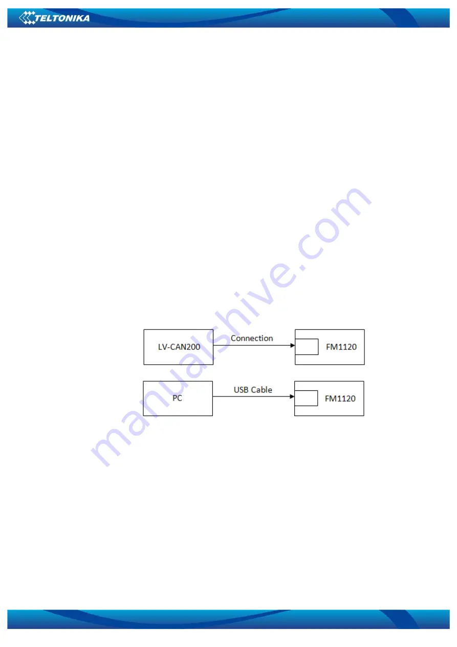
To configure CAN data:
1.
In car, connect LV-CAN200 to CAN bus and to the FM1120 device (Figure 50), wait 10
seconds. Note, that car engine must be started.
2.
Disconnect LV-CAN200 from FM1120, and connect PC USB cable to FM1120 Device
(Figure 51). It is very important not to disconnect FM1120 from power source, because
then all CAN data will be lost.
Figure 55 Connect adapter LV-CAN200 to FM1120
Figure 56 Connect FM1120 to PC and configure
CAN bus data which can be read from your car is shown in “Light Vehicles Can adapter
supported cars” document.
Offline configuration
– user can select which CAN data can be read from LV-CAN200 need
to be sent to server without connection to adapter. Please note that parameters depend on
vehicle manufacturer and vehicle model. Please for further information check “Light Vehicles Can
adapter supported cars” document.
There are two types of operations with CAN data elements:
Monitoring of CAN bus data
CAN bus data event capturing


