background image

TV

Mode

71

3.3.3.1.2.- Combo (Television - Spectrum)

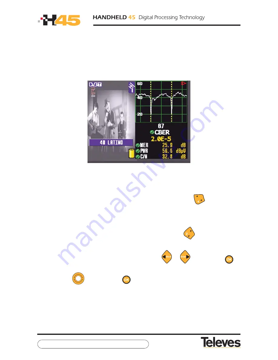
Using this mode, 

we can view the television image, the spectrum and the measures on any

given channel at the same time

.

The meter screen is divided into two sides: on the left side we can see the TV image, and on
the right we can see the spectrum and measures on the channel.

-

Combo mode -

We can commute between analog and digital channel by pressing key 

. For the analog

channels, the measures shown are: 

the level, V/A

(terrestrial only) 

and C/N

. For the digital

channels, the measures shown are: 

CBER, MER, C/N, channel power and C/N Line.

(In the

case of   DVB-S2, CBER is replaced by Linkmargin).

We can commute between terrestrial and satellite channel pressing 

.

In the event it is a digital channel and the equipment has obtained services, we can change

service (if the menus are hidden) by using the cursor keys 

or 

, or by pressing 

, in

which case we will be shown a list of the services offered by this channel. To browse this list

we can use the 

, pressing button 

to choose a given service.

Summary of Contents for H45 Compact

Page 1: ...w w w t e l e v e s c o m V 1 0 User Manual ...

Page 2: ......

Page 3: ... 1 3 3 AUDIO CARRIER 3 3 1 4 MEASURE PARAMETERS 3 3 1 5 QUALITY PROFILES 3 3 1 6 LOGGER MEMORIES 3 3 1 6 1 MEMORIES 3 3 1 6 1 1 RECUPERATION 3 3 1 6 1 2 RECORDING 3 3 1 6 1 3 ERASE 3 3 1 6 1 4 EDIT NAME 3 3 1 6 2 MACROMEASURES 3 3 1 6 2 1 EXECUTING MACROMEASURES 3 3 1 6 2 2 CREATING MACROMEASURES 3 3 1 6 2 3 ERASING MACROMEASURES 3 3 1 6 2 4 EDITING A NAME 3 3 1 6 2 5 MACRO EDITING 3 3 1 6 3 DATAL...

Page 4: ...MODE 3 3 3 1 VIEWING MODE 3 3 3 1 1 SYNCHRONISM 3 3 3 1 2 COMBO MODE 3 3 3 1 3 TELETEXT 3 3 3 2 MEASURES 3 3 3 2 1 ANALOGS 3 3 3 2 1 1 LEVEL 3 3 3 2 1 2 V A 3 3 3 2 1 3 C N 3 3 3 2 1 4 CNLINE 3 3 3 2 1 4 1 LINE CNLINE 3 3 3 2 1 5 FIELD STRENG 3 3 3 2 2 DIGITAL 3 3 3 2 2 1 DVB T 3 3 3 2 2 1 1 PARAMETERS 3 3 3 2 2 1 2 BER 3 3 3 2 2 1 3 MPEG 3 3 3 2 2 1 4 CONSTELLATION 3 3 3 2 2 1 4 1 ZOOM 3 3 3 2 2 ...

Page 5: ...3 4 2 SPAN 3 3 4 3 MEASURES 3 3 4 3 1 ANALOGS 3 3 4 3 1 1 LEVEL 3 3 4 3 1 2 V A 3 3 4 3 1 3 C N 3 3 4 3 1 4 FIELD STRENG 3 3 4 3 1 5 BANDWIDTH 3 3 4 3 2 DIGITAL 3 3 4 3 2 1 POWER 3 3 4 3 2 2 C N 3 3 4 3 2 3 BANDWIDTH 3 3 4 3 3 SATELLITE IDENT 3 3 4 4 MARKERS 3 3 4 4 1 MARKER A 3 3 4 4 2 SEARCH FOR PEAKS 3 3 4 4 2 1 MAX PEAK 3 3 4 4 2 2 NEXT PEAK 3 3 4 5 2 3 PREVIOUS PEAK 3 3 4 5 2 4 UPPER PEAK 3 3...

Page 6: ...LINE 3 4 ERROR MESSAGES 4 INPUT AND OUTPUT DESCRIPTIONS 4 1 RF INPUT 4 2 USB PORT 4 3 MINI DIN 4 4 OPTICAL INPUT 4 5 HDMI 5 MAINTENANCE 5 1 BATTERY REPLACEMENT 5 2 CLEANING RECOMMENDATIONS 5 2 1 CLEANING OPTICAL EQUIPMENT 6 122 123 123 124 126 126 126 127 127 128 129 129 131 131 ...

Page 7: ...mber that rms voltages over 60 V DC or 30 V AC are potentially dangerous At all times maintain the maximum environmental conditions specified for the apparatus The operator is only authorized to intervene in order to replace the battery The Maintenance section gives specific instructions for this procedure Any other change in the equipment must be carried out exclusively by specialized personnel W...

Page 8: ...is can be seen in figure Connection to the mains 1 2 2 Battery A Lithium battery with nominal tension 7 2V and 9 A H is supplied with the H45 This battery with combined average consumption gives the equipment over 4 hours of autonomy The equipment incorporates a complex battery charging and discharging system that optimizes its duration and active life preventing sudden reductions of the equipment...

Page 9: ...the charge level is under 25 the LED will be on for 500 msec and off for 2 5 sec As it charges the on time will go increasing and the off time diminishing When the charge reaches 75 the LED will stay on for 2 5 sec and off for 500 msec When it is completely charged the LED will remain permanently on while the equipment is in use If the battery charge drops below 5 the icon filling will appear in r...

Page 10: ...move the 6 screws Change the battery and connecting Covering the battery again Connecting the DC power for 8 hours to charge the battery If the charging management system detects any condition preventing the initiation of the charging process the latter will not start This may occur due to excessive battery temperature maximum charging time ...

Page 11: ...sing the DC adaptor supplied with the equipment or powering it with DC voltage within the specified range 12V 15V This is the only way to guarantee its durability and active life 1 3 STARTUP To start up the equipment press the ON button Once this has been pressed all the equipment s LEDs will be illuminated for a few seconds During this interval the meter will show the Televés logo and the softwar...

Page 12: ...re in spectrum Satellite 860 MHz 2220 MHz Measure in analog Measure and demodulation DVB S Measure and demodulation DVB S2 Dinamic range Terrestrial 50 dB Satellite 45 dB Measurements and applications Viewing Analyzer TV Combo Analyzer TV simultaneous measures Multinorm PAL B G D K I SECAM B G D K L Units dBµV dBmV dBm dBµV m Standard precision 1dB Terrestrial 2dB Satellite Quality Check Marks Pow...

Page 13: ...tellation DVB T2 MPEG2 MPEG4 DVB C BER 1 0E 2 1 0E 8 DVB C MER DVB C Power 40 125 dBµV DVB C Constellation DVB C MPEG2 MPEG4 DVB C CAM DVB S CBER 1 0E 2 1 0E 6 DVB S BER 1 0E 4 1 0E 8 DVB S MER DVB S Power 40 120 dBµV DVB S MPEG2 MPEG4 DVB S CAM DVB S2 Link Margin 1 10dB DVB S2 CBER 1 0E 2 1 0E 8 DVB S2 BCH BER 5 0E 2 1 0E 8 DVB S2 MER DVB S2 Power 40 120 dB DVB S2 Constellation DVB S2 MPEG2 MPEG4...

Page 14: ...eed 250 ms Screen refresing speed 250 ms Maximum Minimum 1 Mark Input Output Screen TFT 5 Mini DIN HDMI Optical connector FC APC RF connector F F interchangeable CAM Speaker External Power USB Mechanical environmental specifications Weight 2 1 Kg without battery Dimensions 306 x 150 x 125 mm Altitude Up to 2000 m Temperature range 0 40 ºC Maximum relative humidity 80 Up to 31ºC Decreasing linearly...

Page 15: ...equency channel symbol rate values Further on the following symbol will be used to indicate the parameters whose values may be introduced using the numerical keyboard Besides some of the numerical keys are also quick keys for certain frequently used functions The paragraphs below provide a detailed explanation of all the functions and those possessing a quick key will be indicated by a symbol on t...

Page 16: ...aragraphs below that explain the meter functions in detail the following symbol will be used to indicate the parameters that may be selected by using the rotating selector Rotating selector 4 Parameter Acceptance Key The key confirms the introduction of the parameter If we are browsing through the menus it will also give us access to the selected sub menu 5 Key This selects the frequency tuning mo...

Page 17: ...channel tuning mode If a measuring window is open it will display the channel that has been tuned If there is no window open the window for the last measurement made will automatically open Once in channel tuning mode if we press the key again we will be able to introduce the desired channel by keying in its name number characters only with the key In satellite mode by steady pressure on key we ca...

Page 18: ...key To turn the equipment off this key should be pressed for over 3 seconds 11 Key It makes the menu buttons appear and disappear on the screen Likewise it is also used to close the windows appearing in the middle of the screen parameter selection windows and to cancel parameters when keyboard values are being inserted 12 Key This key has two functions if the user is introducing data with the nume...

Page 19: ...GENERAL Switches between FM terrestrial and satellite 22 Key SHORT PRESS TV MODE Switches between Analyzer Combo Mode and TV mode LONG PRESS Press and hold the key TV MODE Switches between TV mode Combo Mode and Analyzer 23 Key SHORT PRESS GENERAL Switches between analogue and digital LONG PRESS Press and hold the key TV MODE TERRESTRIAL Allows one to activate the analogue digital channel identifi...

Page 20: ...Key SHORT PRESS TV MODE Next channel search ANALYZER Satellite identification LONG PRESS Press and hold the key TV MODE Previous channel search 26 Key SHORT PRESS GENERAL Access to the screen controls LONG PRESS Press and hold the key GENERAL Access to the satellite positioning function 27 Key SHORT PRESS TV MODE Records ILOG screen measurements In echo visualisations it records the trace 20 ...

Page 21: ...rted once the temperature reaches a certain threshold the process will abort and resume automatically when the temperature returns to previous values Providing external power is connected to the equipment battery charging will take place If we interrupt the battery charging process by pressing the following key for more than 3 seconds the battery charge will not reinitiate until we again press the...

Page 22: ... malfunction When the equipment is reset it acquires the status it had the last time it was shut down normally To activate this button a non piercing object must be used at adequate pressure 32 Optical 599022 599023 599024 599025 33 Mini DIN 34 HDMI 35 CAM CAM module slot 36 RF Input Signal input connector with 75 ohm impedance 22 ...

Page 23: ...r External input power 12 14 8 V 39 USB port Connection to PC to use the HSuite program and or meter software updating On the sides we have 40 Ventilators They maintain the optimal functioning temperature for the equipment 23 ...

Page 24: ...il you press button Selection of options using cursors Inter menu browsing is carried out by using the set of keys providing the menus are visible or no option has been pressed The viewing and hiding of the menus may be done using the key The following keys are used to browse the current menu and The selected menu function will be marked as shown in the image deselecting the function which had pre...

Page 25: ...n immediately previous one use key If the equipment is in TV mode the measures will appear superimposed on the image and may be hidden by pressing In the analyzer mode and in the combo mode the measures are always visible enabling the user in the analyzer mode to simultaneously see the measures he wishes to carry out and the spectrum of the signal Besides in the combo mode the user will see the me...

Page 26: ...V A C N C N L FIELD STRENGTH ANALOG DIGITAL A D AUTO DVB T T2 DVB C DVB S DVB S2 PARAMETER BER MPEG CONSTELL ECHOES PARAMET BER MPEG CONSTELL PARAMET BER MPEG LANGUAGE ENERGY OPTIONS MONITOR PARAMET ROTATING SELECTOR CLOCK VIDEO IN OUT OSD STYLE EQUIPMENT INFO VOLUME BRIGHTNESS CONTRAST COLOUR HIGH VISIBILITY UPDATE CHANGE BATTERY EXTENDED INFO FACTORY SETTINGS EQUIPMENT CONFIG ENERGY MANAG AUTO S...

Page 27: ...h the frequency of the video carrier of any channel When there is a measurement window open and the frequency tuning mode has been selected if we press the key we will go to the channel tuning mode and see the channel tuned on the window The frequency shown is that of the video carrier of the channel that was tuned by analog mode and the central frequency of the channel in the digital mode By turn...

Page 28: ...n will disappear and then we can introduce the frequency using the numerical keyboard and confirm the frequency by pressing Within the satellite band and in the frequency tuning mode if we carry out prolonged depression of the key we will alternate between Real Frequency and FI ...

Page 29: ...One may select different options in each menu by using the or the cursor keys when they are active The cursors will always be active when the menu is hidden or when a menu option has been pressed Within this option we have the following sub menu Measures configuration 3 3 1 1 Band Change terrestrial This enables choosing one of the following bands terrestrial satellite and FM radio It may be noted...

Page 30: ...This option varies depending on whether the terrestrial or satellite band has been selected In the terrestrial band when this function has been selected a window will automatically open by which the installer may select the voltage of the pre amplifiers This window is shown below When the meter is on the option that appears selected will always be OFF A short pressure on the key alternates between...

Page 31: ...mming is associated with the band chosen for the equipment so if one chooses 24V in terrestrial this will not imply that the same voltage will be used for satellite The equipment continually monitors the voltage through the F connector and warns of any anomaly using a message window that is overprinted on any other open window The possible problems that may appear in relation to external unit powe...

Page 32: ...y and band of the satellite As well as the chosen polarity and band the multi switch should be provided with information on the satellite we intend to work with the multi switches group the different polarities in groups The equipment detects voltage in the coaxial cable In this case the message that will appear is Vext This situation should be avoided When the equipment detects a short circuit it...

Page 33: ... appear Satellite selection in the Multi switch We will choose the right satellite An 8 1 input multi switch will only offer satellites A and B Once chosen we will press The equipment will proceed to send the command that informs the satellite multi switch as well as the required band and polarity previously selected in LoadVDC When one of the inputs of DiSEqC is selected if the external unit powe...

Page 34: ...ELLITE Mode and feeding LNB otherwise the equipment will inform us with the appropriate error messages Only Satellite No Diseqc Vdc OFF respectively we get a dropdown menu with the ability to select SCR channels from SCR 1 to SCR 8 Moving the and pressing key we select the SCR slot that we want to deactivate Choosing from the SCR OFF list all SCR slots will be deactivated as well as the SCR SCR ch...

Page 35: ...pears in the upper right corner with the flashing SCR indicator In analyzer and combo mode the traze colour of the spectrum becomes blue Both the channel mode as the frequency mode we can see the SCR CHANNEL that is currently selected The SCR mode indicator Channel SCR0 SCR1 SCR2 SCR3 SCR4 SCR5 SCR6 SCR7 Frequency MHz 1680 1420 2040 1210 1680 1420 2040 1210 ...

Page 36: ...tandard selection 3 3 1 3 2 Selecting a Plan This selects the channel plan that the user chooses One plan can be selected for terrestrial and another for satellite The options we will have are the following Terrestrial band CCIR STDL OIRT CCIR IT FCC DAB SIM7637 Satellite band AMAZONAS AMAZONASC ASTRA19 ASTRA23 ASTRA28 ATL BIRD3 ATL BIRD3C BARD26 EUROBIRD EUTELSAT7 EUTELW2 EUTELW3A HELLAS HISPASAT...

Page 37: ...y 3 3 1 3 3 Audio Carrier The options appearing in this function will depend on the color standard that has been selected To select a user desired option you may use the As well as the sound carrier frequencies for each standard the window offers the option Other PAL B G 5 50 y 5 74 PAL D K 6 50 y 6 74 PAL I 6 00 SECAM B G 5 50 y 5 74 SECAM L 6 50 y 5 85 SECAM D K 6 50 y 5 85 If LNB power is neces...

Page 38: ...ier selection window will close and a window will open in which the user can select another frequency comprised within 4 00 and 9 00 by using the Audio carrier To close this window use the key You may only select Audio Carrier in Terrestrial Analog mode ...

Page 39: ... frequency which may be Intermediate Frequency IF or Real Frequency LNB Type This option may only be modified if Real Frequency has previously been selected in the option Satellite Frequency enabling the choice of LNB type Universal LNB It is the right one for the Ku Band oscillator frequencies will be 9 750 and 10 600 GHz the real frequency range extends from 10 7 to 12 8 GHz Band C Oscillator fr...

Page 40: ...g or stopping of the equipment AUTO or whether it should be permanently stopped OFF Combo mode with prior startup It is recommended to set the Amplifier stage at OFF when the total voltage at meter input is over 90 dBµV When the option is in AUTO and the meter considers it necessary to start up the stage it will show that it is active with a blinking red icon ...

Page 41: ... dBm This is used in high power devices such as transmitters and re transmitters 3 3 1 5 Quality Profiles Using this menu we can choose between the different profiles that establish the limits for the quality indicators This means that users can choose a different profile depending on their requirements The device has 2 pre installed profiles socket and headend Users may configure up to four profi...

Page 42: ...ries These functions are 3 3 1 6 1 Memories One MEMORY enables the saving and recuperation of equipment configurations The H45 enables the saving of up to 250 1000 different configurations memories according to equipment version for your equipment that you may easily recuperate The meter is capable of storing any status such as mode standard measure type etc List of available memories ...

Page 43: ...nd the menu shown in the previous Figure will appear Then press option RECORD The memory list will be located at the end of the menu and the name of the next free memory will appear blinking on and off The memory name appearing by default is always MEM followed by three digits in ascending numerical order on the list but the user may give any desired name to the memory This gives us four possibili...

Page 44: ...then press This function is particularly used when we want to measure installations with a great number of sockets and with a SAT TV distribution system consisting of DiSEqC selectable multi switches Each time a MEMORY is executed the meter will automatically generate the corresponding DiSEqC commands and store the measurements offering a significant time savings when measuring this kind of instal...

Page 45: ...list When you find one of the memories to be erased press and this memory will be highlighted If you wish to select all the memories of the meter you can use the option SELECT ALL and all the memories will be highlighted Once you have finished selecting press the option CONFIRM to erase the memories you have selected On confirming memory erasure the following message will appear on screen MEMORY E...

Page 46: ...ed this space will remain blank When the desired character appears in the desired position simply press the button or and the process will start anew with the next character in the name If you wish to return to the previous character press the key on the keyboard The name of each memory must posses between 1 and 7 characters Name editing ends once the 7 characters of the name have been edited If t...

Page 47: ...asures of up to 250 memories each can be configured The meter is capable of measuring from a list of memories every time this is necessary and the results may be shown on the display of the meter itself or downloaded to the computer A DATALOG is a listing of the results measurements obtained on automatically executing a Macromeasure once or twice The meter enables the storage of multiple different...

Page 48: ...ing Macromeasures This function is used to enable the Macromeasure to run through all the associated memories and record the results on a LOG Executing a Macromeasure You can execute a Macromeasure as many times as needed Before starting the process of measurement recording the meter shows a configuration window on the execution of the Macromeasure ...

Page 49: ...first executes the FM memory then the terrestrial one and finally the satellite memory Log Options This option enables the selection of a previously created LOG or starting a new one New Log Each time the Macromeasure is executed the meter will create a new Log to store the results the measurements Summary Log The meter will store the results of the Macromeasure in the desired Log Edit Log Name Wi...

Page 50: ...measures from the meter memories The meter can store up to 100 lists Macromeasures of different memories which can include up to 250 memories each When we press function Create the meter proposes a new name for the Macromeasure Later we can change it by using the function Edit Name described below Creating a Macromeasure ...

Page 51: ...name of a Macromeasure To change the name we browse through the list of Macromeasures using the and press key To change each position we will use the and we can use keys or to browse through the text 3 3 1 6 2 5 Macro Editing The Macro Editing function enables one to change the Memories associated with a Macromeasure We may therefore include new Memories or remove Memories from the Macromeasure Th...

Page 52: ...will be shown DATALOGS The DATALOGS are the measures that the meter has saved when carrying out one of the following functions Macromeasure or SCAN LOG The measures of a Macromeasure are identifiable as being composed of two parts the first identifies the saved LOG name and the second column indicates the name of the macromeasure In the event there is no DATALOG stored in the meter s memory the me...

Page 53: ...r the purpose on we will find DATALOGS selecting and deselecting them with button The save marked will be shown in yellow and then we will press the option CONFIRM ending the erasure operation by once again pressing the button the message DATALOG ERASED appearing on screen 3 3 1 6 3 2 Editing DATALOGS From this option we can change the name of the desired DATALOG at any moment For the purpose by u...

Page 54: ... different available options and press the button if we wish to enable the option chosen In the diagram one can see three different columnss The first one on the left with the heading Socket has two verification boxes that indicate the type of socket we have The one indicating Ter Sat is really for those installations where the satellite and terrestrial signal are on different sockets therefore wh...

Page 55: ...the search range at which the SCAN LOG will start to measure the different channels To change this range we must press over the search range TERRESTRIAL and SATELLITE and with the we can enter a value between 40 and 120 dBµv or the OFF value to deactivate the function There is a separate search range for terrestrial bandwidth and satellite This range is also used in the manual search function usin...

Page 56: ...ls found and the measurements on those channels Using the we can browse through them seeing the measurement parameters If we are interested in tuning in a channel on the list all we need do is select with and press button 3 3 1 6 3 4 INSTANT LOG Thanks to the Instant Log function the meter can record the measurements that are currently being seen in DATALOG format Direct access to this function ca...

Page 57: ...surements are being made the parameters evaluated are level and C N The sound signal variation is as follows If the field meter is in the spectrum analysis mode the function takes as its reference the reference level that has been selected This means that the tone will be more high pitched the closer to reference values in level or power in the case of analog or digital measures respectively The i...

Page 58: ... H45 gives you the ability to select menu language The languages available are Spanish English Portuguese French German Italian Polish and Russian The following window opens when you select this menu Selection of available menu languages 3 3 2 2 Energy Options In this menu one has various functions for managing the H45 meter s energy ...

Page 59: ...L mode Energy management 3 3 2 2 2 Automatic Sleep Mode The unit has a sleep option which can be programmed to activate once the idle time has lapsed The idle time can be programmed from 1 to 59 minutes The user may also deactivate this function OFF The default idle time is set at 10 minutes Once the idle time has lapsed the meter will enter sleep mode The screen will turn off and the flickering L...

Page 60: ...ty cutoff period 3 3 2 3 Monitor parameters This groups the functions controlling monitor parameters volume brightness contrast color and high visibility The window appearing when enabling these functions is similar in every case It is a horizontal bar whose length varies with the level of the selected parameter To vary the value of these parameters you may use the To accept the selected value you...

Page 61: ...2 3 2 Brightness Quick Key This increases or reduces the brightness of the image on screen It works in a similar way to the volume control 3 3 2 3 3 Contrast Quick Key This increases or reduces the contrast of the image on screen It works in a similar way to the volume control 3 3 2 3 4 Color Quick Key This increases or reduces the color intensity of the image on screen It works in a similar way t...

Page 62: ...following window opens Clock option This sets time hour and minutes and date day of the month month and year The user need only press key and current hour lights up dark blue background frame By turning the time changes Pressing the new hour is set and the process is repeated for minutes Pressing a third time you select the day of the month and lastly you select the year The day of the week varies...

Page 63: ... video output Mini DIN connector LCD Optimal operation mode LCD and HDMI connector brings out the video with a resolution of 640x480 60Hz HDMI Enables HDMI video output with a resolution of 720x576 60Hz so the image on the LCD is clipped It is important to check the status of Input mode selection since if the On option is selected we will not be able to see the TV signal on screen when we want to ...

Page 64: ... that will be made are those corresponding to the input signal of the F connector No measurements can be made with the Mini DIN signal The same thing happens in regard to the spectrum depiction of the signal i e although the image displayed on the screen is from the Mini DIN the spectrum will be that corresponding to the RF input signal The only exception to the above is the display of the synchro...

Page 65: ...nt information When you select this function a window will open showing equipment information as shown below Equipment Information Window 3 3 2 8 1 Updating Using this option we can upload the license number enabling an option package Serial Number Model ...

Page 66: ...2 Select the function Battery change A confirmation request for the change will then be displayed on the screen To confirm the change you must press the key if any other key is pressed instead of this one the change will be cancelled Battery change information window 3 Turn off the equipment 4 Disconnect the equipment from the power grid This function must be used only and exclusively when a batte...

Page 67: ... be taken when replacing battery Both when removing the battery from the equipment and when reconnecting it make sure that the meter is turned off If the battery is removed from the equipment when it is replaced make sure that it is properly reconnected If metal tools are used for battery installation the battery must be insulated because a short circuit might occur Do not connect the positive and...

Page 68: ...TV Mode 68 To confirm the change you must press the key if any other key is pressed instead the change will be cancelled ...

Page 69: ...the following 3 3 3 1 Viewing Mode By using the functions of this sub menu we can select the items we wish to be displayed on the meter screen synchronism impulse television line combo television spectrum and teletext 3 3 3 1 1 Synchronism In this case what is viewed is the representation of the synchronism impulse on the right side of the screen To stop viewing the synchronism impulse simply pres...

Page 70: ...TV Mode 70 Syncronism ...

Page 71: ...nalog channels the measures shown are the level V A terrestrial only and C N For the digital channels the measures shown are CBER MER C N channel power and C N Line In the case of DVB S2 CBER is replaced by Linkmargin We can commute between terrestrial and satellite channel pressing In the event it is a digital channel and the equipment has obtained services we can change service if the menus are ...

Page 72: ...n level is 1 5 Teletext window We can browse through the teletext pages using the We will be able to directly access a teletext page by pressing the key and then introducing the page number If we press the teletext key again viewing will end The teletext may only be viewed in Television MPEG or Combo mode Viewing of Teletext can only be done from the Television MPEG or Combo modes The key is a qui...

Page 73: ... the frequency information appearing on the window is erased Then you may type in the frequency using the keyboard It is important to remember that for decimal point insertion you should also use the key To introduce the channel using the keyboard press the key when in the channel mode and type in the digits for the desired channel In the event that more than one channel possesses the same digits ...

Page 74: ...d window contains the following information Name of the measure selected Value of the measurement Frequency or channel on which the measurement is taken Previous power Channel Plan Tone 22KHz Color standard only terrestrial band Audio carrier only terrestrial band Bandwidth of the measurement filter Bar for main measurement selected graphically shows the quality of the signal According to its colo...

Page 75: ...den 3 3 3 2 1 1 Level If the channel tuning mode is selected this function will measure the level of the carrier for the tuned channel Contrarily if the frequency tuning mode is selected the window will show the signal level of the tuned frequency The tuned frequency can be varied by using the in the terrestrial band with a resolution of 50 KHz and satellite also 50 KHz or by using the numerical k...

Page 76: ...ay vary the tuning by using the or the numerical keyboard V A Measure Tuning by frequency If we press the key the information on the tuned channel will appear In this case the frequency on which the video level measurement is being made will be the video carrier of the channel that the equipment will automatically seek Therefore when the equipment is in frequency tuning mode it is the user s respo...

Page 77: ...y tuning is used the level measurement is made on the frequency tuned by the user and will depend on that frequency corresponding with the real carrier of the channel 3 3 3 2 1 4 C N line dB Measurement that indicates the quality of the analogue image This measurement corresponds to the sound carrier relationship but synchronised to a specific TV line line 3 and line 25 By default the selected lin...

Page 78: ...ne C N line This function allows one to change the line with which one synchronises the meter to in order to carry out the C N line measurement Use the to switch between line 3 and line 25 and confirm by pressing the key C N Line ...

Page 79: ... cable For the H45 this unit is calculated for a Televes DAT HD antenna and 10 meters of cable T100 for more information please visit http www televes com Field Strength ICT legislation establishes minimum standards that must be taken at the point of signal collection In the case of terrestrial television you can see the following table Signal Type Frequencies MHz Field Strength Analog 470 582 65 ...

Page 80: ...re To show whether the selected measure is within the acceptable threshold bar fullness and color vary There is also a graphic indicator associated with each measure showing if it is at an acceptable threshold Its color changes through red yellow and green with the same meaning as the color of the bar associated with the measure When the bar is red this shows that the signal quality in that measur...

Page 81: ...rs On selecting this menu a new window opens over that of the BER measures on which appears the list of parameters that may be selected To select the parameter to be modified use the pressing to confirm selection Then a window opens showing the list with all the possible values for this parameter The parameters that can be varied in DVB T are Bandwidth from 7 0 to 8 0 MHz and AUTO Number of Carrie...

Page 82: ...ormation on the constellation used for each carrier and the code rate as well as the cell identifier Cell Id In the Offset section if the frequency of the COFDM channel has shifted an offset may be applied 0 1 6 2 6 3 6 1 6 2 6 3 6 Auto to correct the shift This will only be valid in the channel mode and is shown under the current DVB T channel selection Possible parameters to be selected with the...

Page 83: ...be viewed is selected The reduced information window shows only the frequency or channel tuned the name of the service selected if it is a garbled channel the character will appear beside the name and the CBER measure of the DVB T signal In the extended information windows the network identifier is also shown if available the number of supplier services and other different items of data on the tun...

Page 84: ...rds AAC EAAC and AC3 The capacity to decode MPEG4 is integrated transparently inside the H45 for users It is compatible with the following modulations DVB T T2 DVB T2 only for 599021 599024 599025 DVB C DVB S and DVB S2 By means of channel services a MPEG 4 service image can be displayed and information about the video and audio can be consulted In the event that no DVB T signal is available the i...

Page 85: ... access module DVB T The H45 meter has a Common Interface slot CI in its higher part where a Conditional Access Module CAM is inserted It is valid for any digital modulation always being compatible with DVB CI and MPEG 2 and MPEG4 services CAM ...

Page 86: ...function represents the DVB T constellation of all the carriers the TPS carriers plus the disperse carriers or of a specific selected carrier As well as this graphic representation the same screen shows the CBER and MER measures of the DVB T signal DVB T Constellation ...

Page 87: ...Carrier The DVB T transmission of any channel is composed of some 8 000 carriers of which there are 6 817 usable ones and they are divided into signal and data carriers This function enables the selection of the carriers to be represented The possibilities are all the carriers TPS carriers plus disperse carriers and a specific carrier For the latter case the carrier number should be introduced usi...

Page 88: ...th different delays and bandwidths This will often help to explain why the BER does not have an acceptable value if we have a good C N and signal level Within the echo visualisation mode there is a menu that allows us to select the x axis units between microseconds or kilometres Depending on the unit selected the zoom menu will allow us to vary the visualisation window between the following values...

Page 89: ...nkMargin Power C N LDPCBER BCHBER and MER DVB T2 Combo Mode 3 3 3 2 2 2 1 Parameters 599021 599024 599025 The modulation parameters can be changed using this function The device can automatically detect all the parameters required for demodulation Once demodulation occurs the parameters are displayed to the right of the word AUTO Carriers 1K 2K 4K 8K 16 K 32 K Extended Mode 8K 16K y 32K Modulation...

Page 90: ...TV Mode 90 DVB T2 Parameters 3 3 3 2 2 2 2 BER 599021 599024 599025 Option Use this feature to go back to the BER measurement window from other windows BER Mode ...

Page 91: ...p to 1080p and is compatible with audio standards AAC EAAC and AC3 Using the rotary switch you will be able to access the list of channel services When the desired service has been found press OK to confirm the selection Then if the service has multiple audio channels available select the desired channel This option offers three different information windows one small and two extended Using the ho...

Page 92: ...representation the calculated LDPCBER and MER measurements are also displayed on the same screen DVB T2 Constellation 3 3 3 2 2 2 4 1 Zoom 599021 599024 599025 on Use this option to select the quadrant for the constellation to be displayed for a detailed view If you select Zoom OFF the on screen graph will cover all four quadrants ...

Page 93: ...Measures The measures available for a DVB C signal are Power C N CBER and MER 3 3 3 2 2 3 1 Parameters The parameters that may be selected for a DVB C signal are Bandwidth from 1 0 to 8 0 MHz and AUTO Symbol Velocity AUTO 6875 6111 5156 4583 5893 5238 6900 OTHER 6875 Constellation 4QAM 16QAM 32QAM 64QAM 128QAM 256QAM OTHER and Spectrum Inversion ON OFF AUTO The way in which these parameters are se...

Page 94: ...tion window shows only the frequency or channel tuned the name of the service selected if it is a garbled channel the character will appear beside the name and the CBER measure of the DVB C signal In the event that no DVB C signal is available the information windows will show UNLOCK In the extended information windows the network identifier is also shown if available the number of supplier servic...

Page 95: ...TV Mode 95 MPEG4 DVB C It works similarly to the MPEG 4 DVB T section MPEG4 Decoding CAM Conditional access module DVB C It works similarly to the CAM DVB T section ...

Page 96: ... this graphic representation the screen shows the CBER and MER of the DVB C signal DVB C Constellation 3 3 3 2 2 3 4 1 Zoom Using this option a quadrant of the constellation to be represented may be selected for more detailed viewing When you select Zoom OFF the on screen graphic will expand to the four quadrants ...

Page 97: ... DVB S are Power C N CBER VBER and MER 3 3 3 2 2 4 1 Parameters The possible parameters that may be selected for a DVB S signal are as follows Bandwidth from 2 0 to 40 0 MHz and AUTO Symbol velocity AUTO 27500 24500 22000 15000 OTHER and Code Rate AUTO 1 2 2 3 3 4 5 6 7 8 The parameters are selected in the same way as previously DVB S Parameter Options Selection of the AUTO mode is recommended for...

Page 98: ...tion window shows only the frequency or channel tuned the name of the service selected if it is a garbled channel the character will appear beside the name and the CBER measure of the DVB S signal In the event that no DVB S signal is available the information windows will show UNLOCK In the extended information windows the network identifier is also shown if available the number of supplier servic...

Page 99: ...TV Mode 99 MPEG4 DVB S It works similarly to the MPEG 4 DVB T section MPEG4 Decoding CAM Conditional access module DVB S It works similarly to the CAM DVB T section ...

Page 100: ...re given CBER MER and BCHBER BCH error correction algorithm bit error rate The available measures for a DVB S2 are Power C N Link Margin BER BCHBER and MER 3 3 3 2 2 5 1 Parameters The only parameter necessary to define for DVB S2 signal measurement is symbol velocity The parameter of speed symbol can be in AUTO mode in this case the meter will automatically identify the symbol rate once found it ...

Page 101: ...hing Serv By using the we can access the list of channel services When we have located the desired service we press the key to confirm the selection Afterwards if there are several available audio channels we can choose among them We will also be able to change services when the menus are hidden This option has three different information windows one of them reduced and two extended Using quick ke...

Page 102: ...ent items of data on the tuned channel in each of the two windows On the first of the windows these data are SID VPID for audio channels value 0 will be shown NID and APID At the bottom of the window audio and video information is shown type of MPEG video resolution and audio channel selected among all the available ones On the second window the respective data are Profile and Level ID video forma...

Page 103: ...ic representation the same screen shows the Link Margin and MER measures of the DVB S2 signal DVB S2 Constellation 3 3 3 2 2 5 4 1 Zoom Using this option a quadrant of the constellation to be represented may be selected for more detailed viewing When you select Zoom OFF the on screen graphic will expand to the four quadrants ...

Page 104: ... meter makes it possible to automatically identify the type of channel analogue or digital The AUTO A D function is only available for the TV mode and Combo mode This mode may also be accessed quickly by holding down the key for more than 1 second A D Auto ...

Page 105: ...ccupied by a channel identifying in the case of the terrestrial band whether it is an analog or digital channel and after tuning in on the channel the meter will adopt the respective setting digital or analog 3 3 3 3 2 Previous channel If we select this function or if we apply prolonged pressure to the key the meter will search for the previous position occupied by a channel identifying in the cas...

Page 106: ...ntral part of the spectrum you will see an interrupted yellow line dashes while if any digital measure is selected this line will not appear being replaced by two interrupted yellow lines at equal distances from the central line of the spectrum The separation between these lines shows the bandwidth of the channel which is selected at that moment Spectrum analyzer mode Frequency tuning analogue cha...

Page 107: ...e channel mode we will go to the next channel and the spectrum will move to the next video carrier The sub menu corresponding to the Analyzer mode is the following Analyzer mode options 3 3 4 1 Reference level This enables the user to choose the reference level the highest level of the spectrum so as to optimize signal spectrum viewing according to level The reference level corresponds to the valu...

Page 108: ...ed by using the or the keys until we confirm by using key or Thereupon the information on the reference level disappears and the information on the selected level reappears Selecting a reference level As the value is changed these changes may be observed in the spectrum This makes it easy to know what the optimal reference level is for viewing the signal spectrum ...

Page 109: ...evel of each horizontal division are in red Likewise the number that indicates the reference level will blink showing the user that he must increase the reference level to avoid saturation A quick way of changing the reference level is by using keys when the menu is hidden thus the reference level may be quickly changed to adapt it to the current signal ...

Page 110: ... the information on the selected measure disappears momentarily being replaced with the information on the span The different options for this parameter will appear on turning the or pressing On pressing key or the selected span is validated and the selected measure reappears The selectable values are 15 10 20 50 100 200 500 SPAN FULL If the menus are hidden you may use the cursor keys to directly...

Page 111: ...istance from the equipment Each measure is associated with a color code enabling the user to make a rapid evaluation of the channel selected 3 3 4 3 1 Analog Measures When this function is selected the meter will carry out analog measurements selecting as its main measure the last one chosen by the user Signal level 3 3 4 3 1 1 Level This is the function used to select the level measure as a main ...

Page 112: ...rier selection is taken as that of the audio carrier this function is in Config Measure Channels Standards Audio Carrier V A Measure 3 3 4 3 1 3 C N In the same way as with the V A measure on selecting this function the main measure becomes the Carrier Noise Power ratio The carrier level is taken on the central frequency and the frequency for measuring the noise power is calculated automatically b...

Page 113: ...nt of the C N since it will be used to correct the value of the noise level measured so as to reference it to the whole bandwidth of the channel When it is selected it will be seen at the bottom right of the screen and the measure selected will momentarily disappear With or the cursors we can vary this parameter and confirm the value by using the keys or Bandwidth change ...

Page 114: ... the measure of power is selected as a main measure and will be seen at the bottom right of the screen In this measure the meter combines the power of the signal comprised between the central frequency minus half the bandwidth of the channel and the central frequency plus half the bandwidth of the channel Power of a digital channel To ensure this measurement is correctly made we must select the co...

Page 115: ...Analyzer 115 3 3 4 3 2 2 C N On selecting the C N measure the meter will show at the lower right of the screen the Channel Power Noise Power ratio C N Measure of a digital channel ...

Page 116: ...tion This function allows one to identify the relevant satellite name for the signal trace seen in analyser mode To get to this function we must be on analyser mode and on satellite band otherwise the meter will advise with the message SATELLITE ONLY Once the function has been activated in analyser mode and both in analogue or digital a flickering message will appear on the bottom right SEARCHING ...

Page 117: ...hese standards and not doing so may result in identification errors Satellite identification 3 3 4 4 Markers The H45 gives you the chance of using one three markers depending on the model in the spectrum Using the functions of this sub menu we can move them throughout the spectrum to carry out level measurements at the marked frequencies The following is the respective sub menu Marker options ...

Page 118: ...Analyzer 118 3 3 4 4 1 Marker A Using this option we enable the yellow marker and to disable it we can select the option again or choose a measure from ANALYZER MEASURES Markers ...

Page 119: ...of the marker Or select using key when the menus are hidden 3 3 4 4 2 3 Previous Peak From the current marker it searches for the previous maximum frequency using the current position of the marker Or select using key when the menus are hidden 3 3 4 4 2 4 Upper Peak From the current marker it searches for the upper maximum frequency using the current position of the marker Or select using key when...

Page 120: ... graph will continue to represent the instant signal Whenever any of the parameters of the spectrum is modified Reference level Span the graph representing the maximums will erase and the maximums will again accumulate as from that moment under the new selection conditions Maximum 3 3 4 5 2 Minimum On Off Using this function you enable disable the representation of minimums On enabling this functi...

Page 121: ...sented on screen Once this function has been selected the information on the measure will disappear in its place showing the dB DIV Using the or with the cursors we can vary this parameter and confirm with the keys or The possible values for this parameter depending on the options are 5 10 dB DIV ...

Page 122: ...n menu use this option to select the input type to make your measurements RF optical When the optical input is selected the meter will show the optical measurement along with any other measurements in all measurement modes Combo Analyzer and TV Optical input The optical measurement will also be recorded in the Datalogs and the graphs Input Selection ...

Page 123: ...plays four options for selection Input signal Selects the input type Optical RF Lambda When the optical input is activated it selects the lambda at which the measurement will be made 1310nm 1490nm or 1550nm Optical drives When the optical input is activated it selects the type of units used dBm mW µW or dB Optical baseline Displays the optical baseline To select a new value use the Set Optical Bas...

Page 124: ...er 3 sec etc In the event that the message remains it is a good idea to turn the equipment off leaving the external powering connected to ease the evacuation of the internal heat ERROR XXXX When the equipment turns on it carries out a self check of all its modules When an anomaly is detected in any of them the message ERROR appears followed by a code If this occurs you should contact your Televés ...

Page 125: ...conds approximately LIMIT EXCEEDED This error message is generated when the power consumption in connector F exceeds the allowable maximum In this case the external unit power cuts off and automatic attempts at restarting are made every three seconds approximately No DiSEqC Vdc off This message appears when an attempt is made to select one of the DiSEqC inputs with the external unit power at OFF p...

Page 126: ...nector can be easily replaced if deteriorated 4 2 USB PORT The H45 has a USB port for data interchange with a PC USB connector type B The signals in this connector are as follows PIN no DESCRIPTION CABLE 1 5Vcc Red 2 Data USB White 3 Data USB Green 4 GND ground Black 1 2 4 3 The maximum signal level should in no case exceed 130 dbµV ...

Page 127: ...o DESCRIPTION 4 4 OPTICAL INPUT 599022 599023 599024 599025 Depending on meter configuration the device can be fitted with an FC APC connector for optical measurements 1 Audio IN 2 Audio OUT 3 Switch SCART 4 Video SCART 5 Video IN SCART 6 TFT B 7 TFT G 8 TFT R 9 RGB ON 10 Masa 1 2 3 4 5 6 7 8 9 ...

Page 128: ... no DESCRIPTION PIN no DESCRIPTION 1 TMDS Data2 2 TMDS Data2 Shield 3 TMDS Data2 4 TMDS Data1 5 TMDS Data1 Shield 6 TMDS Data1 7 TMDS Data0 8 TMDS Data0 Shield 9 TMDS Data0 10 TMDS Clock 11 TMDS Clock Shield 12 TMDS Clock 13 CEC 14 Reserved N C on device 15 SCL 16 SDA 17 DDC CEC Ground 18 5 V Power max 50 mA 19 Hot Plug Detect 1 2 18 19 3 5 7 9 11 13 15 17 4 6 8 10 12 14 16 ...

Page 129: ...ly reduced To guarantee its proper functioning it should be supplied by Televés who should provide adequate protection for it For battery replacement follow the procedure illustrated below Turn off the equipment and disconnect the external power Remove the rear cover of the equipment unscrewing the six screws that keep it in place 1 2 ...

Page 130: ...les leading from the battery since the high level of the current from it could cause serious damage to the equipment WARNING Precautions to be taken when replacing battery Both when removing the battery from the equipment and when reconnecting it make sure that the meter is turned off If the battery is removed from the equipment when it is replaced make sure that it is properly reconnected If meta...

Page 131: ...ys keep unused connectors covered with the provided dust caps Clean connectors frequently especially after disconnecting reconnecting or manipulating the connectors Properly handle connectors and patch cords used Fibre Cleaning Kit To clean the housing make sure the equipment is disconnected Do not use aromatic hydrocarbons or chlorinated solvents for cleaning These liquids can attack the material...

Page 132: ...ontinue with the cleaning process otherwise dispose of the fibre Use a cleaning swab specifically designed to clean optical connectors Do not touch the cleaning tip Swabs are single use only Do not reuse Moisten the swab with isopropyl alcohol or a cleaning solvent specifically formulated to clean optical connectors Carefully insert the cleaning swab into the connector and gently rotate clockwise ...

Page 133: ... to inspect fibre condition If the fibre only needs cleaning you can continue with the cleaning process otherwise dispose of the fibre a Using cleaning wipes Gently clean the fibre ends using wipes pre moistened with isopropyl alcohol or appropriate solvent Dry off by using a clean dry wipe Cleaning with a wipe ...

Page 134: ...Advance the tape mechanism to have a fresh area of the cleaning tape exposed in the connector cleaning window Slide the fibre on the window in the direction of the arrow Use a microscope to check the cleaning job Cleaning with tape ...

Page 135: ...in force at the time of purchase is applied Keep the purchase invoice to determine this date During the guarantee period Televés S A becomes position of the failures produced by defect of the material or manufacture The harm produced by improper usage wear and tear manipulation by a third party catastrophes or any other cause beyond the control of Televés S A is not included in the guarantee GUARA...

Page 136: ...to use final product It is hereby notified that a license for such use are required from Dolby Laboratories Dolby Digital Plus Dolby and the double D symbol are trademarks of Dolby Laboratories This product contains one or more programs protected under international and U S copyright laws as unpublished Works They are confidential and propietary to Dolby Laboratories Their reproduction or disclosu...

Page 137: ...137 ...

Page 138: ...138 ...

Page 139: ......

Page 140: ... TELEVES CHINA Unit 207 208 Building A No 374 Wukang Rd Xuhui District 200031 Shanghai CHINA P R C Telephone 86 21 6126 7620 Fax 86 21 6466 6431 EMail shanghai televes net cn Rúa Benéfica de Conxo 17 15706 Santiago de Compostela ESPAÑA SPAIN Tel 34 981 52 22 00 Fax 34 981 52 22 62 televes televes com www televes com Sucursales Distributors Para conocer nuestra red de sucursales en el mundo le roga...

Reviews: