background image

107

2.7.1

System Settings

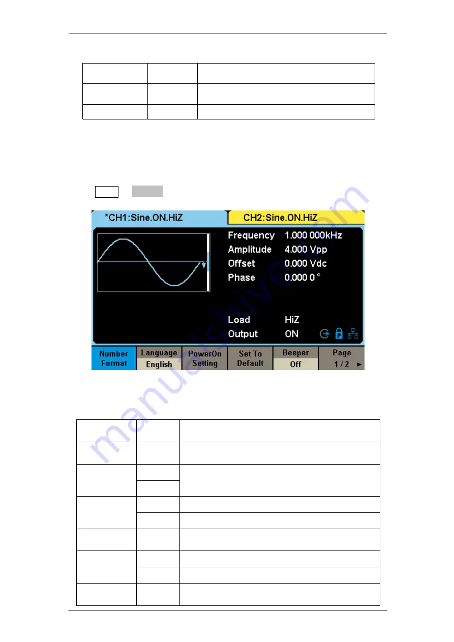
Press Utility → System, to enter the following interface.

Table 2-29 Menu Explanations of System Setup (Page 1/2)

Function
Menu

Settings

Explanation

Number
format

Set the number format.

Language

English

Set the language.

Chinese

PowerOn

Default

All the settings return to default when power on; Last

All the settings return to the setting of last power on.

Set to
Default

Set all the settings to default.

Beeper

On

Open the beeper.

Off

Close the beeper.

Page

1/2

Enter the next page.

Table 2-31 Menu Explanation of Utility (Page 3/3)

Function
Menu

Settings

Explanation

Multi-Device
Sync

Multi-Device Synchronization setting

Page 3/3

Return to Page 1

Figure 2-48 System Setup Interface (Page 1/2)

Summary of Contents for T3AFG Series

Page 1: ...User Manual T3AFG200 350 500 Series Function Arbitrary Waveform Generator ...

Page 2: ...I Declaration Copyright Teledyne Test Tools All rights reserved Without permission contents in this manual are not allowed to be copied extracted or translated ...

Page 3: ... is grounded correctly before connecting its input or output terminals Connect the signal wire correctly The potential of the signal wire ground is equal to the earth therefore do not connect the signal wire to a high voltage Do not touch the exposed contacts or components Observe all terminal ratings To avoid fire or electric shock please observe all ratings and sign instructions on the instrumen...

Page 4: ...UBLE INSULATION PROTECTIVE EARTH TERMINAL This electronic product is subject to disposal and recycling regulations that vary by country and region Many countries prohibit the disposal of waste electronic equipment in standard waste receptacles For more information about proper disposal and recycling of your Teledyne LeCroy product visit teledynelecroy com recycle Rated for indoor use only Do not o...

Page 5: ... meet the growing requirements for a multitude of complex applications Key Features Dual channel 500MHz maximum bandwidth 20Vpp maximum output amplitude output with 80dB dynamic range High performance sampling system with 1 2GSa s sampling rate and 16 bit vertical resolution No detail in your waveforms will be lost They also include proprietary TrueArb EasyPulse technology that help to solve the w...

Page 6: ...n Waveforms combining function Channel Coupling Copy and Tracking function High precision Frequency Counter 196 kinds of built in arbitrary waveforms Standard interfaces USB Host USB Device USBTMC LAN VXI 11 Socket Telnet 4 3 touch screen display for easier operation ...

Page 7: ... 1 To Set Sine Waveform 18 2 1 2 To Set Square Waveform 23 2 1 3 To Set Ramp Waveform 26 2 1 4 To Set Pulse Waveform 28 2 1 5 To Set Noise Waveform 32 2 1 6 To Set DC Waveform 36 2 1 7 To Set Arbitrary Waveform 37 2 1 8 To Set Pseudo Random Binary Sequence PRBS 47 2 1 9 To Set Harmonic Function 51 2 2 To Set IQ Waveform Optional 54 2 2 1 Front Panel IQ Control 54 2 2 2 EasyIQ Software 59 2 3 To Se...

Page 8: ...ne Waveform 146 3 2 Example 2 Generate a Square Waveform 148 3 3 Example 3 Generate a Ramp Waveform 150 3 4 Example 4 Generate a Pulse Waveform 152 3 5 Example 5 Generate a Noise 154 3 6 Example 6 Generate a Pseudo Random Binary Sequence 155 3 7 Example 7 Generate a Linear Sweep Waveform 157 3 8 Example 8 Generate a Burst Waveform 159 3 9 Example 9 Generate an AM Modulation Waveform 161 3 10 Examp...

Page 9: ... Generate an IQ Waveform 177 4 Troubleshooting 179 4 1 General Inspection 179 4 2 Troubleshooting 180 5 Service and Support 181 5 1 Maintenance summary 181 5 2 Contact Teledyne Test Tools 182 6 Appendix 183 Appendix A Accessories 183 Appendix B Daily Maintenance and Cleaning 184 ...

Page 10: ...k Start This chapter covers the following topics Handle Adjustment The Front Rear Panel To Select a Waveform To Set Modulation Sweep Burst To Turn On Off Output To Use Numeric Input To Use Common Function Keys ...

Page 11: ...dle Adjustment To adjust the handle position of T3AFG please grip the handle by the sides and pull it outward Then make the handle rotate to the desired position Figure 1 1 Viewing Position and Carrying Position ...

Page 12: ...anel Front Panel The T3AFG has a clear and simple front panel which includes 4 3 inch touch screen menu softkeys numeric keyboard knob function keys arrow keys and channel control area etc Figure 1 2 Front Panel of T3AFG200 350 500 USB Host Numeric Keyboard Knob Power Key User Interface Menu Softkeys Function Keys Channel Control Arrow Keys ...

Page 13: ...l provides multiple interfaces including Counter 10MHz In Out Aux In Out LAN USB Device Earth Terminal and AC Power Supply Input Figure 1 3 Rear Panel of T3AFG200 350 500 Aux In Out 10 MHz Clock Input Earth Terminal LAN Interface AC Power Supply Input Counter ...

Page 14: ... use your finger or touch pen to control the instrument Most functions and selections can be chosen using the touch screen in a similar manner to front panel keys and knob Figure 1 4 TouchScreenDisplay 1 Waveform Display Area Displays the currently selected waveform of each channel 2 Channel Status Bar Indicates the selected status and output configuration of the channels Click here twice and a sh...

Page 15: ... and 50Ω High Impedance display HiZ and assumes a load impedance of 1 MΩ Load display impedance value the default is 50Ω and the range is 50Ω to 100kΩ Note This setting does not actually change the instrument s output impedance of 50Ω but rather is used to maintain amplitude accuracy into different load values Output Channel output state After pressing corresponding channel output control port the...

Page 16: ...rent clock source is from an external clock source 8 Menu Shows the menu corresponding to the displayed function For example Figure 1 4 Touch Screen Display shows the parameters of AM modulation Click menu options on the screen to select and set the corresponding parameters 9 Modulation Parameters Area Shows the parameters of the current modulation function After selecting the corresponding menu u...

Page 17: ...from 1μHz to 500MHz By setting Frequency Period Amplitude High level Offset Low level and Phase a sine wave signal with different parameters can be generated Figure 1 6 Sine Display Interface 2 Press Waveforms key and then press Square softkey The generator can generate square waveforms with frequencies from 1μHz to 120MHz and variable duty cycle By setting Frequency Period Amplitude High level Of...

Page 18: ...itude High level Offset Low level Phase and Symmetry a ramp waveform with different parameters can be generated Figure 1 8 Ramp Display Interface 4 Press Waveforms key and then press Pulse softkey The generator can generate pulse waveforms with frequencies from 1μHz to 150MHz and variable pulse width and rise fall times By setting Frequency Period Amplitude High level Offset Low level PulWidth Dut...

Page 19: ...he generator can generate noise with bandwidth from 80MHz to 500MHz By setting Stdev and Mean noise with different parameters can be generated Figure 1 10 Noise Display Interface 6 Press Waveforms key and then press Page 1 2 last press the DC softkey The generator can generate a DC signal with a level up to 10V into a HighZ load or 5V into a 50Ω load ...

Page 20: ...ple rate from 1 μSa s to 300 MSa s in TrueArb mode By setting Frequency Period Amplitude High level Offset Low level Phase and Arb Mode an arbitrary signal with different parameters can be generated Figure 1 12 Arbitrary Waveform Display Interface Press Waveforms Page 1 2 I Q then CH1 and CH2 output orthogonal I and Q signals respectively and channel status bar displays In phase and Quadrature sep...

Page 21: ...Signal Display Interface Press Waveforms Page 1 2 PRBS and channel status bar displays PRBS The generator can generate a Pseudo Random Bit Sequence PRBS with bit rates ranging from 1 μbps to 300 Mbps By setting BitRate Period Amplitude High level Offset Low level Length Logic Level and Rise Fall A PRBS with different parameters can be generated Figure 1 14 PRBS Display Interface ...

Page 22: ...PM ASK FSK PSK PWM and DSB AM etc Pulse waveforms can only be modulated using PWM Noise and DC waveforms cannot be modulated Figure 1 14 Modulation Display Interface 1 4 To Set Modulation Sweep Burst As shown in Figure 1 13 there are three keys on the front panel which are used for modulation sweep and burst settings The instructions below will help to explain these functions Figure 1 13 Modulate ...

Page 23: ...1μs to 1000s Figure 1 16 Burst Waveform Display Interface 2 Press Sweep the Sweep function will be enabled Sine square ramp and arbitrary waveforms support the sweep function In sweep mode the T3AFG can generate signals with variable frequency The available range of sweep time is from 1ms to 500s The trigger source can be Internal External or Manual Figure 1 15 Sweep Waveform Display Interface ...

Page 24: ...s the arrow keys are used to select the digit to be modified When using numeric keyboard to set parameters the left arrow key is used as a Backspace function 1 5 To Turn On Off Output As shown in Figure 1 17 there are two keys on the right side of the operation panel which are used to enable disable the output of the two channels Choose a channel and press the corresponding Output key the key back...

Page 25: ...ters of basic waveforms directly 2 The Utility key is used to set the auxiliary system function such as output configurations interface setting system setting information performing the instrument self test and reading the calibration information etc 3 The Store Recall key is used to store and recall waveform data and configuration information 4 The Waveforms key is used to select basic waveforms ...

Page 26: ...uggested to read chapter one Quick Start again This chapter covers the following topics To Set Sine To Set Square To Set Ramp To Set Pulse To Set Noise To Set DC To Set Arbitrary To Set Harmonic Function To Set IQ Waveform To Set Modulation Function To Set Sweep Function To Set Burst Function To Store and Recall To Set Utility Function It is recommended that you read this chapter carefully so as t...

Page 27: ...select Frequency The frequency parameter area is highlighted in the parameter display window users can set the frequency value here Figure 2 1 Sine Parameters Display Interface Table 2 1 Menu Explanations of Sine Waveform Function Menu Explanations Frequency Period Set the signal frequency or period The current parameter will be switched at a second press Amplitude HighLevel Set the signal amplitu...

Page 28: ...r than Frequency is the desired parameter press Frequency Period again to enter the Period mode The current value for the waveform s period is now displayed in inverse color Press the Frequency Period key once again to return to the Frequency entry mode 2 Input the desired frequency Use the numeric keyboard to input the parameter value directly and press the corresponding key to select the paramet...

Page 29: ...ress the Amplitude HighLevel key again to switch into the high level parameter the current operation is displayed in inverse color 2 Input the desired amplitude Use the numeric keyboard to input the parameter value directly and press the corresponding key to select the parameter unit Or use the arrow keys to select the digit to edit and then use the knob to change its value Figure 2 3 Setting the ...

Page 30: ... keyboard to input the parameter value directly and press the corresponding key to select the parameter unit Or use the arrow keys to select the digit to edit and then use the knob to change its value Figure 2 4 Setting the Offset To Set the Phase 1 Press Waveforms Sine Phase to set the phase The Phase shown on the screen when the instrument is powered on is the default value or the set value of l...

Page 31: ...22 select the digit to edit and then use the knob to change its value Figure 2 5 Setting the Phase Note When the independent mode is enabled the phase parameter cannot be modified ...

Page 32: ...eter display window and users can set the duty cycle value here Figure 2 6 Square Parameters Display Interface Table 2 2 Menu Explanations of Square Waveform Function Menu Explanation Frequency Period Set the signal frequency or period The current parameter will be switched at a second press Amplitude HighLevel Set the signal amplitude or high level The current parameter will be switched at a seco...

Page 33: ...0 1 Press Waveforms Square DutyCycle to set the duty cycle The duty cycle shown on the screen when the instrument is powered on is the default value or the set value of last power down 2 Input the desired Duty Cycle Use the numeric keyboard to input the parameter value directly and press the corresponding key to select the parameter unit Or use the arrow keys to select the digit to edit and then u...

Page 34: ...25 Figure 2 7 Setting the Duty Cycle Note The methods of setting other parameters of square signal are similar to sine waveform function ...

Page 35: ...in the parameter display window and users can set the symmetry value here Figure 2 8 Ramp Parameters Display Interface Table 2 3 Menu Explanations of Ramp Waveform Function Menu Explanation Frequency Period Set the signal frequency or period The current parameter will be switched at a second press Amplitude HighLevel Set the signal amplitude or high level The current parameter will be switched at ...

Page 36: ...e or the set value of last power down 2 Input the desired Symmetry Use the numeric keyboard to input the parameter value directly and press the corresponding key to select the parameter unit Or use the arrow keys to select the digit to edit and then use the knob to change its value The generator will change the waveform immediately Note The methods of setting other parameters of the ramp signal ar...

Page 37: ...rameters Display Interface Table 2 4 Menu Explanations of Pulse Waveform Function Menu Explanation Frequency Period Set the signal frequency or period The current parameter will be switched at a second press Amplitude HighLevel Set the signal amplitude or high level The current parameter will be switched at a second press Offset LowLevel Set the signal offset or low level The current parameter wil...

Page 38: ...ative Once a parameter is changed the other will be automatically changed 1 Press Waveforms Pulse PulWidth to set the pulse width The pulse width shown on the screen when the instrument is powered on is the default value or the set value of last power down If you want to set the waveform by duty press the PulWidth DutyCycle key again to switch into the duty cycle parameter the current operation is...

Page 39: ...rms Pulse Rise to set the rise edge The rise edge shown on the screen when the instrument is powered on is the default value or the set value of last power down If you want to set the waveform by fall edge press the Rise Fall key again to switch into the fall edge parameter the current operation is displayed in inverse color 2 Input the desired rise edge Use the numeric keyboard to input the param...

Page 40: ...31 Figure 2 12 Setting the Rise Edge Note The methods of setting other parameters of pulse signal are similar to sine waveform function Refer to To Set the Sine Waveform to configure other parameters ...

Page 41: ...ter area is highlighted in the parameter display window and users can set the stdev value here Noise is non periodic signal which has no frequency or period Figure 2 13 Noise Parameters Display Interface Table 2 5 Menu Explanations of Noise To Set the Stdev 1 Press Waveforms Noise Stdev to set the stdev Function Menu Explanation BandSet Turn on off the bandwidth setting Stdev Setting the stdev for...

Page 42: ...e digit to edit and then use the knob to change its value To Set the Mean 1 Press Waveforms Noise Mean to set the mean The mean shown on the screen when the instrument is powered on is the default value or the set value of last power down 2 Input the desired mean Use the numeric keyboard to input the parameter value directly and press the corresponding key to select the parameter unit Or use the a...

Page 43: ...lue or the set value of last power on When changing the function if the current value is valid for the new waveform it will be used sequentially 2 Input the desired bandwidth Use the numeric keyboard to input the parameter value directly and press the corresponding key to select the parameter unit Or you can use the arrow keys to select the digit you want to edit and then use the knob to change it...

Page 44: ...35 Figure 2 16 Setting the Bandwidth ...

Page 45: ...forms Page 1 2 DC to enter the following interface Please note that there is a DC offset parameter at the middle of the screen Figure 2 17 DC Setting Interface Note The method of setting offset of DC signal is similar to sine wave function ...

Page 46: ...d in the internal non volatile memory TrueArb output mode allows creation of arbitrary waveforms that contain from 2 to 20 Mpts TrueArb Choose Waveforms Page 1 2 Arb Arb Mode and select the TrueArb output mode The parameters include frequency period amplitude high level offset low level and phase and interpolation Figure 2 18 Arb Parameters Display Interface TrueArb ...

Page 47: ...r Linear Page 2 2 Return to the previous page To Set the Sampling Rate In TrueArb output mode users can set the sampling rate the output points per second or frequency of the arbitrary waveform The instrument outputs an arbitrary waveform point by point with the current sampling rate Press Waveforms Page 1 2 Arb TrueArb SRate to set the sampling rate parameter When changing parameter if the new va...

Page 48: ...t mode The parameters include frequency period amplitude high level offset low level and phase Figure 2 20 Arb Parameters Display Interface DDS In DDS output mode users can set the frequency or period of the arbitrary waveform The instrument outputs an arbitrary waveform which is made up of certain points according to the current frequency ...

Page 49: ...ary Waveforms Press Common Math Engine Window Trigo or other menus to switch to the desired category the selected category in the menu bar is highlighted then rotate the knob or click the touch screen to choose the desired waveform the selected waveform will be highlighted Select Accept or press the knob to recall the corresponding waveform StairUp Stair up waveform StairDn Stair down waveform Sta...

Page 50: ...ichlet function Erf Error function Erfc Complementary error function ErfcInv Inverted complementary error function ErfInv Inverted error function Laguerre 4 times Laguerre polynomial Legend 5 times Legend polynomial Versiera Versiera Sinc Sinc function Gaussian Gaussian function Dlorentz Dlorentz function Haversine Haversine function Lorentz Lorentz function Gauspuls Gauspuls signal Gmonopuls Gmon...

Page 51: ...gOsc Kinetic energy time curve of swing oscillation Discharge Discharge curve of NI MH battery Pahcur Current waveform of DC brushless motor Combin Combination function SCR SCR firing profile TV TV signal Voice Voice signal Surge Surge signal Radar Analog radar signal Ripple Ripple wave of battery Gamma Gamma signal StepResp Step response signal BandLimited Bandwidth limited signal CPulse C Pulse ...

Page 52: ...in tapered cosine window Trigo Tan Tangent Cot Cotangent Sec Secant Csc Cosecant Asin Arc sine Acos Arc cosine Atan Arc tangent ACot Arc cotangent CosH Hyperbolic cosine CosInt Integral cosine Coth Hyperbolic cotangent Csch Hyperbolic cosecant SecH Hyperbolic secant SinH Hyperbolic sine SinInt Integral sine TanH Hyperbolic tangent ACosH Arc hyperbolic cosine ASecH Arc hyperbolic secant ASinH Arc h...

Page 53: ...y32 Square waveform with 32 duty SquareDuty34 Square waveform with 34 duty SquareDuty36 Square waveform with 36 duty SquareDuty38 Square waveform with 38 duty SquareDuty40 Square waveform with 40 duty SquareDuty42 Square waveform with 42 duty SquareDuty44 Square waveform with 44 duty SquareDuty46 Square waveform with 46 duty SquareDuty48 Square waveform with 48 duty SquareDuty50 Square waveform wi...

Page 54: ...quare waveform with 94 duty SquareDuty96 Square waveform with 96 duty SquareDuty98 Square waveform with 98 duty SquareDuty99 Square waveform with 99 duty Medical EOG Electro Oculogram EEG Electroencephalogram EMG Electromyogram Pulseilogram Pulseilogram ResSpeed Speed curve of the respiration ECG1 Electrocardiogram 1 ECG2 Electrocardiogram 2 ECG3 Electrocardiogram 3 ECG4 Electrocardiogram 4 ECG5 E...

Page 55: ...utterworth Butterworth filter Chebyshev1 Chebyshev1 filter Chebyshev2 Chebyshev2 filter Demo demo1_375pts TureArb waveform 1 375 pts demo1_16kpts TureArb waveform 1 16384 pts demo2_3kpts TureArb waveform 2 3000 pts demo2_16kpts TureArb waveform 2 16384 pts 2 To Select the Stored Waveform Choose Waveforms Page 1 2 Arb Arb Type Stored Waveforms to enter the following interface as shown in Figure 2 2...

Page 56: ...h logic level and rise fall Figure 2 23 PRBS setting interface Table 2 8 Menu Explanations of PRBS Function Menu Explanation BitRate Period Set the signal bit rate or period Amplitude HighLevel Set the signal amplitude or high level Offset LowLevel Set the signal offset or low level Length Set the length of PRBS Logic Level Set the logic level of PRBS Rise Fall Set the rising and falling edge of P...

Page 57: ... the value will be set Otherwise the nearest valid value will be set If Period rather than BitRate is the desired parameter press BitRate Period again to enter the period mode Figure 2 24 Setting the Bit Rate To Set the Length Press Waveforms Page 1 2 PRBS Length to set the length parameter The range of length is from 3 to 32 When changing parameter if the new value is valid the value will be set ...

Page 58: ...ponding type of logic level the high level and low level of PRBS can be configured automatically If Differential is set to ON channel one will output the waveform with normal polarity while channel two will output the waveform with inverted polarity Figure 2 25 Setting the Length Figure 2 26 Setting the Logic Level ...

Page 59: ...6V LVDS 1 6V 900mV To Set the Rise Fall Edge Press Waveforms Page 1 2 PRBS Rise Fall to set the rise fall edge parameter When changing parameter if the new value is valid the value will be set Otherwise the nearest valid value will be set Note The methods of setting other parameters of the PRBS are similar to the sine waveform function Refer to To Set the Sine Waveform to configure other parameter...

Page 60: ... fundamental waveform frequency A1 is fundamental waveform amplitude and φ1 is fundamental waveform phase The frequencies of the other components harmonics are all integral multiples of the fundamental waveform Components whose frequencies are odd multiples of the fundamental waveform frequency are called odd harmonics and components whose frequencies are even multiples of the fundamental waveform...

Page 61: ...ven harmonics 2 Press Odd the instrument will output fundamental waveform and odd harmonics 3 Press All the instrument will output fundamental waveform and all the user defined orders of harmonics To Set the Harmonic Order After entering the harmonic setting menu press Order the use the numeric keyboard or knob to input the desired value 1 The range is limited by the maximum output frequency of th...

Page 62: ...The units available are Vpp mVpp and dBc To Select the Harmonic Phase After entering the harmonic setting menu press Harmonic Phase to set the harmonic phase of each order 1 Press Order to select the sequence number of the harmonic to be set 2 Press Harmonic Phase to set the phase of the harmonic selected Use the arrow keys and knob to change the value Or use the numeric keyboard to input the phas...

Page 63: ...to the T3AFG through a USB or LAN device interface Figure 2 29 IQ modulation 2 2 1 Front Panel IQ Control Press Waveforms key to select the waveform function and then press the I Q softkey The IQ waveform parameters are set by using the IQ operation menu In IQ mode the two channel output one I Q pair and all the parameters are set for the I Q pair The parameters available for IQ waveforms include ...

Page 64: ...l whose center frequency is the intermediate frequency The figure below shows the diagram of the IQ modulator in the T3AFG Figure 2 31 Figure 2 31 IQ Modulator in the T3AFG To Set the Fsymb Fs Fsymb symbol rate can be transformed to Fs sampling frequency according to the Oversampling factor Pts Symbol The formula below shows the relationship Fs Fsymb Pts Symbol The range of Fs is from 500 Hz to 75...

Page 65: ...e amplitude When the unit is Vrms mVrms or dBm the amplitude equal to the modulus of the I Q Figure 2 33 Setting the Amplitude To Set the Trigger Source Press Parameter Trigger Source to set the Trigger Source including internal trigger external trigger and manual trigger as shown in Figure 2 34 ...

Page 66: ... input 5V CMOS pulse with the specified polarity 3 Manual Trigger Choose Trigger Source Manual and one period of the IQ waveform will be generated once the Trigger softkey is pressed I Q Data Choose Parameter I Q Data to select the built in waveforms or the stored waveforms 1 Built in Waveforms Choose Parameter I Q Data Built in to select a built in IQ waveform including ASK PSK and QAM Choose the...

Page 67: ...lso be copied to the instrument by a USB flash disk I Q Adjustment Choose Parameter I Q Adjustment to enter the adjustment interface as show in Figure 2 35 The adjust parameters include Gain Balance I Q Offset and Angle Adjustment Detailed description is shown in the table below Table 2 11 IQ Adjustment Parameters Parameter Explanation Gain Balance Amplitude gain balance adjusting the difference b...

Page 68: ...ata Source Modulation and Filter as shown in Figure 2 36 Figure 2 36 EasyIQ Interface 2 2 2 1 Data Source Data Source panel sets parameters for the symbol data that is to be modulated As show in Figure 2 37 in the Data Source console you can set the data setup symbol length and symbol rate Figure 2 37 EasyIQ Data Source Setting ...

Page 69: ...at will repeat itself after its period User File When selecting User File as data source type a file selection dialog box pops up for you to select a TXT txt file as input data bits In the user data file only 0 or1 is acceptable Any other characters are illegal and an error message box will pop up Customer Bit Pattern When selecting Customer Bit Pattern as data source type a Pattern Editor window ...

Page 70: ...1000000 Symbol s Bits Per Symbol Displays the number of bits contained in one modulated symbol It is read only not settable 2 2 2 2 Modulation Modulation panel sets parameters for user selected modulation type Figure 2 39 Modulation Interface Choices APSK QAM MFSK Multitone Custom Default APSK QAM APSK QAM Selects a type in APSK QAM category for modulation Choices 2ASK 4ASK 8ASK BPSK QPSK 8PSK DBP...

Page 71: ...ellation you can also double click on the zoomed constellation window to close it Gray Turns ON or OFF the Gray code for the constellation data Default OFF MFSK Selects a type in MFSK category for modulation Choices 2FSK 4FSK 8FSK 16FSK MSK Default 2FSK 2FSK 4FSK 8FSK 16FSK When selecting 2FSK 4FSK 8FSK 16FSK as current modulation type FSK FSK Dev Hz Sets frequency deviation for FSK modulation in ...

Page 72: ... the multi tone signal Below is the interpretion for the multi tone parameters Sample Rate sample rate of multi tone modulation in MHz Range 0 002 to 37 5 MHz Default 2 MHz Freq Spacing frequency spacing of multi tone modulation in MHz Range 0 to Sample Rate 1 28 MHz Default 1 MHz Tone Number tones number of multi tone modulation Range 1 to 20 Default 1 Single Side Turns ON or OFF single side modu...

Page 73: ...nstellation point manually You can also recall constellation data from an existing file and save the edited constellation data to a new file Normalize button is used to normalize all constellation data for RMS value 1 On the right side of the window it shows the constellation display of current editing You can input a name for the constellation this name will be displayed beside the Custom modulat...

Page 74: ...osine filter root raised cosine filter and Gaussian filter To interface is shown in Figure 2 42 Filter Type Sets filter type for current modulation Choices None RaisedCosine RootCosine Gaussian Default Gaussian for MSK and RootCosine for all other modulation types Note For MSK modulation only Gaussian filter type is supported Filter Alpha BT Sets the Alpha factor of the filter BT of Gaussian filte...

Page 75: ...f the main window You can click FFT Spectrum or IQ Waveform tab to display the Frequency domain waveform or Time domain waveform alternatively Notes 1 Right click on the waveform display to hide the display You can click Update button or the FFT Spectrum IQ Waveform tab to show the waveform plot again 2 When the Mouse is on waveform display you can use the scroll button of your Mouse to zoom in or...

Page 76: ...44 Time domain Waveform The I Q data plots are displayed separately in two graphs The horizontal coordinate shows the symbol values and the vertical coordinate shows the amplitude values of I Q data 2 2 2 5 Waveform Download Click the button on the top of the window the download interface is displayed as shown in Figure 2 45 You can download the IQ baseband data generated from current settings or ...

Page 77: ...ctly in the VISA Address drop down list the USBTMC Visa address of the T3AFG will be displayed as shown in Figure 2 46 Select the address and click the download button to download the waveform data Figure 2 46 Download Data through USB Device Figure 2 45 Download Interface LAN If the T3AFG is connected to the PC through LAN correctly input the IP ...

Page 78: ...69 address of the T3AFG to replace the LOCALHOST characters as shown in Figure 2 47 And then click the download button to download the waveform data Figure 2 47 Download Data through LAN ...

Page 79: ...rnal external modulating frequency frequency deviation modulating waveform and carrier In PM users can set the source internal external phase deviation modulating frequency modulating waveform and carrier In ASK users can set the source internal external key frequency and carrier In FSK users can set the source internal external key frequency hop frequency and carrier In PSK users can set the sour...

Page 80: ...of AM modulation are shown in Figure 2 24 Function Menu Settings Explanation Type AM Amplitude modulation Source Internal The source is internal External The source is external Use the Aux In Out connector at the rear panel AM Depth Set the modulation depth Shape Sine Choose the modulating waveform Square Triangle UpRamp DnRamp Noise Table 2 10 Menu Explanations of the AM Parameters Figure 2 24 Se...

Page 81: ...d Note Noise can be used as modulating waveform but cannot be used as the carrier 2 External Source When external AM modulation source is selected the generator accepts external modulating signal from the Aux In Out connector at the rear panel At this time the amplitude of the modulated waveform is controlled by the signal level applied to the connector For example if the modulation depth is set t...

Page 82: ...0 modulation the output amplitude is the half of the carrier s amplitude In the 120 modulation the output amplitude is the same with the carrier s amplitude For an external source the depth of AM is controlled by the voltage level on the connector connected to the Aux In Out 6V correspond to 100 depth When external modulation source is selected this menu is hidden To Set Modulation Frequency When ...

Page 83: ...e Internal The source is internal External The source is external Use the Aux In Out connector at the rear panel DSB Freq Set the modulating waveform frequency Frequency range 1mHz 1MHz internal source only Shape Sine Choose the modulating waveform Square Triangle UpRamp DnRamp Noise Arb Table 2 11 Menu Explanations of the DSB AM Parameters Figure 2 25 Setting Interface of DSB AM Modulation Note T...

Page 84: ... FM modulation are shown in Figure 2 26 Function Menu Settings Explanation Type FM Frequency modulation Source Internal The source is internal External The source is external Use the Aux In Out connector at the rear panel Freq Dev Set the frequency deviation Shape Sine Choose the modulating waveform Square Triangle UpRamp DnRamp Noise Table 2 12 Menu Explanations of the FM Parameters Figure 2 26 S...

Page 85: ... this time the frequency of the modulated waveform is controlled by the signal level applied to the connector For example if the frequency deviation is set to 1 kHz the output frequency will increase 1 kHz based on the carrier frequency setting when the modulating signal is 6 V and decrease 1 kHz when the modulating signal is 6 V To Set Frequency Deviation Press FM Dev to highlight the parameter a...

Page 86: ... PM modulation are shown in Figure 2 27 Function Menu Settings Explanation Type PM Phase modulation Source Internal The source is internal External The source is external Use the Aux In Out connector at the rear panel Phase Dev Phase deviation ranges from 0 360 Shape Sine Choose the modulating waveform Square Triangle UpRamp DnRamp Noise Table 2 13 Menu Explanations of the PM Parameters Figure 2 2...

Page 87: ...m the Aux In Out connector at the rear panel At this time the phase of the modulated waveform is controlled by the signal level applied to the connector For example if the phase deviation is set to 180 the output phase will increase 180 when the modulating signal is 6 V and decrease 180 when the modulating signal is 6 V To Set Phase Deviation Press Phase Dev to highlight the parameter and then use...

Page 88: ...he source is internal External The source is external Use the Aux In Out connector at the rear panel Key Freq Set the frequency at which the output frequency shifts between the carrier frequency and the hop frequency internal modulation only 1mHz 1MHz Hop Freq Set the hop frequency Table 2 14 Menu Explanations of the FSK Parameters Figure 2 28 Setting Interface of FSK Modulation To Select Modulati...

Page 89: ... frequency and hop frequency Use the numeric keyboard or arrow keys and knob to input the desired value The key frequency ranges from 1mHz to 1MHz When external modulation source is selected this menu is hidden To Set Hop Frequency The range of the hop frequency depends on the carrier frequency currently selected Press Hop Freq to highlight the parameter and then use the numeric keyboard or arrow ...

Page 90: ...ulation Source Internal The source is internal External The source is external Use the Aux In Out connector at the rear panel Key Freq Set the frequency at which the output amplitude shifts between the carrier amplitude and zero internal modulation only 1mHz 1MHz Note The methods for setting the parameters of ASK are similar to AM In addition the external modulating signal of ASK must comply with ...

Page 91: ...0 Function Menu Settings Explanation Type PSK Phase shift keying modulation Source Internal The source is internal External The source is external Use the Aux In Out connector at the rear panel Key Freq Set the frequency at which the output phase shifts between the carrier phase and 180 internal modulation only 1mHz 1MHz Polarity Positive Set the modulating polarity Negative Table 2 16 Menu Explan...

Page 92: ...responds to modulating phase output if the polarity is negative the situation is the opposite When external modulation is selected if the polarity is positive logic low of the input corresponds to carrier phase output and logic high corresponds to modulating phase output if the polarity is negative the situation is the opposite Note The way of setting the parameters of PSK is similar to FSK In add...

Page 93: ...1 Function Menu Settings Explanation Type PWM Pulse width modulation The carrier is pulse Source Internal The source is internal External The source is external Use the Aux In Out connector at the rear panel Width Dev Set the width deviation Duty Dev Set the duty deviation Shape Sine Choose the modulating waveform Square Triangle UpRamp DnRamp Noise Table 2 17 Menu Explanations of the PWM Paramete...

Page 94: ... Duty Deviation Press Width Dev or Duty Dev to highlight the parameter and use the numeric keyboard or arrow keys and knob to input the desired value Width Deviation represents the maximum variation of the modulated waveform pulse width relative to the original pulse width The width deviation cannot exceed the current pulse width The width deviation is limited by the minimum pulse width and curren...

Page 95: ...planations of Sweep Page 1 2 Funtion Menu Settings Explanantion Sweep time The time span of the sweep in which the frequency changes between the start frequency to stop frequency Start Freq Mid Freq The start frequency of the sweep The center frequency of the sweep Stop Freq Freq Span The stop frequency of the sweep The frequency span of the sweep Source Internal Choose internal source as a trigge...

Page 96: ...u wish to adjust the period of a waveform press the softkey below the Frequency Period menu label until Period is highlighted and then enter the value Table 2 19 Menu Explanations of Sweep Page 2 2 Function Menu Settings Explanation Type Linear Set the sweep with linear profile Log Set the sweep with logarithmic profile Direction Up Sweep upward Down Sweep downward Up_Down Sweep upward then downwa...

Page 97: ...ency and Frequency Span Center Frequency Start Frequency Stop Frequency 2 Frequency Span Stop Frequency Start Frequency Sweep Type The T3AFG provides Linear and Log sweep profiles and the default is Linear Linear Sweep In linear sweep the output frequency of the instrument varies linearly in the way of a number of Hertz per second Choose Sweep Page 1 2 Type Linear there is a straight line displaye...

Page 98: ...cating that the output frequency changes in a logarithmic mode Figure 2 37 Log Sweep Interface The formula below shows the relationship between frequency f and time t in a logarithmic mode Where fstart is the Start Frequency fstop is the Stop Frequency and tsweep is the Sweep Time Sweep Trigger Source The sweep trigger source can be internal external or manual The generator will generate a sweep o...

Page 99: ...rigger signal inputted from the Aux In Out connector at the rear panel when external trigger is selected A sweep will be generated once the connector receives a CMOS pulse with specified polarity To set the CMOS pulse polarity choose Edge to select Up or Down 3 Manual Trigger Choose Source Manual a sweep will be generated from the corresponding channel when the Trigger softkey is pressed when manu...

Page 100: ...ons among burst type trigger source and carrier N Cycle In N Cycle mode the generator will output waveform with a specified number of cycles after receiving the trigger signal Waveforms that support N Cycle burst include sine square ramp pulse and arbitrary Press Burst NCycle Cycles and use the numeric keyboard or arrow keys and knob to input the desired cycles Set the waveform parameters by using...

Page 101: ...burst Burst Period Set the burst period Source Table 2 21 Menu Explanations of the N Cycle Burst Page 1 2 Function Menu Settings Explanation NCycle Use the N Cycle mode Cycles Infinite Internal Choose internal source as a trigger External Choose external source as a trigger Use the Aux In Out connector at the rear panel Manual Trigger a burst by manual Page 1 2 Enter the next page ...

Page 102: ...e 2 2 Return to the previous page Gated In gated mode the generator controls the waveform output according to the gate signal level When the gated signal is true the generator outputs a continuous waveform When the gated signal is false the generator f i r s t completes the output of the current period and then stops Waveforms that support gated burst include sine square ramp pulse noise and arbit...

Page 103: ...ger External Choose external source as a trigger Use the Aux In Out connector at the rear panel Start Phase Start point of the burst waveform When Burst is enabled press Start Phase and then use the numeric keyboard or the knob to input the desired phase the default value is 0 and the available range is from 0 to 360 For Sine Square and Ramp 0 is the point where the waveform passes through 0 V or ...

Page 104: ...row keys and knob to input the desired value Burst Period 0 99μs carrier period burst number If the current burst period set is too short the generator will increase this value automatically to allow outputting the specified number of cycles Cycles Infinite Set the number of waveform cycle in an N Cycle 1 to 1 000 000 or Infinite If Infinite is chosen then a continuous waveform will be generated o...

Page 105: ...ed Choose Trig Out as Up or Down the Aux In Out connector at the rear panel will output a trigger signal with specified edge 2 External Trigger Choose Source External the generator accepts the trigger signal inputted from the Aux In Out connector at the rear panel when external trigger is selected A burst will be generated once the connector gets a CMOS pulse with specified polarity To set the CMO...

Page 106: ...igure 2 42 Store Recall Interface Page 1 2 Table 2 24 Menu Explanation of Save and Recall Function Menu Settings Explanation File Type State The setting of the generator Data Arbitrary waveform file Browse View the current directory Save Save the waveform to the specified path Recall Recall the waveform or setting information in the specific position of the memory Delete Delete the selected file P...

Page 107: ...les to C Disk 2 USB Device 0 There is a USB Host interface located on the left side of the front panel which permits users to store recall waveforms or update the firmware version by U Disk When the generator detects a USB storage device the screen will show the drive letter USB Device 0 and display a prompt message USB Function Menu Settings Explanation Copy Copy the selected file Paste Paste the...

Page 108: ...ed the name may be displayed in the store and recall interface abnormally Browse Use the knob to shift between the directories or click the corresponding location on the screen to choose Local C or USB Device 0 Choose Browse press the knob or click the selected folder to open the current directory Use the knob to switch between folder and files under the current directory Choose Browse press the k...

Page 109: ...s of two channels and utility parameters Data File The T3AFG can recall the data files in csv or dat format from the external memory and transfer them into bin format then store them in the internal memory When it is done the generator will enter the arbitrary waveform interface automatically In addition users can edit arbitrary waveforms with PC software download them to the internal memory throu...

Page 110: ... and other utility settings used To save the instrument state the procedures are given as followed 1 Choose the file type to store Press Store Recall File Type State and choose state as the storage type 2 Choose the location of the file Choose a desired location by rotating the knob or clicking the corresponding location on the touch screen 3 Name the file Press Save to enter the following interfa...

Page 111: ...tion of the character on the screen directly Then choose Select to display the character selected in the filename area Delete the character Use the left and right arrow keys to move the cursor in the file name Then choose Delete to delete the corresponding character 4 Save the file After finishing inputting filename press Save The generator will save the file under the currently selected directory...

Page 112: ...a the procedures are as follows 1 Choose the file Rotate the knob or click the touch screen to select the file you want to delete 2 Delete the file Choose Delete the generator will display prompt message Delete the file Then press Accept the generator will delete the currently selected file To Copy and Paste File T3AFG supports the internal and external storage to copy files from each other For ex...

Page 113: ...vice 0 and press the knob to open its directory Then rotate the knob to select the file you want to copy and press Page 1 2 Copy 3 Paste the file Rotate the knob to select Local C and press the knob to open its directory Then press Paste ...

Page 114: ... shown in Figure 2 46 and Figure 2 47 Function Menu Explanation System Set the system configuration Test Cal Test and calibrate the instrument Counter Frequency counter setting Output Setup Set the output parameters of CH1 and CH2 CH Copy Coupling Set the track channel coupling or channel copy function Page 1 3 Enter the next page Table 2 27 Menu Explanations of Utility Page1 3 Figure 2 46 Utility...

Page 115: ...anation Interface Set the parameters of remote interfaces Sync Set the sync output CLKSource Internal Choose the system clock source External Help View the help information OverVoltage Protection Turn on off the over voltage protection function Page 2 3 Return to the previous page Figure 2 48 Utility Setup Interface Page 3 3 ...

Page 116: ...rOn Default All the settings return to default when power on Last All the settings return to the setting of last power on Set to Default Set all the settings to default Beeper On Open the beeper Off Close the beeper Page 1 2 Enter the next page Table 2 31 Menu Explanation of Utility Page 3 3 Function Menu Settings Explanation Multi Device Sync Multi Device Synchronization setting Page 3 3 Return t...

Page 117: ...e the screen saver 5min 15min 30min 1hour 2hour 5hour Off Disable the screen saver System Info View the system information Firmware Update Update the firmware by the U disk Help View the help information UI Style Set the UI style Page 2 2 Return to the previous page 1 Number Format Press Utility System Number Format to enter the following interface Normal Classical ...

Page 118: ...se the Separator Space Use Space as the separator Done Save the current settings and return tothe System menu The format can have various forms depending on the choice of the decimal point and the separator 2 Language Setup The T3AFG offers two languages English and Simplified Chinese Press Utility System Language to select the desired language This setting is stored in non volatile memory and wil...

Page 119: ... the T3AFG setting when the generator is powered on Three choices are available Default Last and User Once selected the settings will be applied when the instrument is powered on This setting is stored in non volatile memory and will not be influenced by the Set To Default operation English Interface ...

Page 120: ...ult Press Utility System Set To Default to set the system to the default setting The default settings of the system are as followed Table 2 32 Factory Default Setting Output Default Function Sine Wave Frequency 1kHz Amplitude Offset 4Vpp 0Vdc Phase 0 Load High Z Modulation Default Carrier 1kHz Sine Wave Modulating 100Hz Sine Wave AM Depth 100 FM Deviation 100Hz ASK Key Frequency 100Hz FSK Key Freq...

Page 121: ...een Saver Enable or disable screen saver Press Utility System Page 1 2 ScrnSvr to select On or Off and the default is Off Screen saver will be on if no action is taken within the time that you have selected Click the touch screen or press any key to resume 7 System Info Select the System Info option of the utility menu to view the generator s system information including startup times software ver...

Page 122: ...the generator 2 Press Utility Page 1 2 Firmware Update Or press Store Recall directly 3 Select the firmware file ADS and choose Recall to update the system software 4 After the updating is finished the generator will restart automatically Note 1 Do not switch off the power during the generator update 2 A configuration file CFG may or may not be included with a given firmware update If a CFG file i...

Page 123: ... enter the following interface Figure 2 54 Help Menu Figure 2 55 Help Menu Explanations Function Menu Explanation UP Cursor upward to select Down Cursor downward to select Select Read the currently selected help information Cancel Exit the built in help system There are 10 topics in the help list You can use the knob and or operation menus to select the help information that you want to read ...

Page 124: ...ure 2 56 Test Cal function Menu Table 2 33 Menu Explanations of Test Cal Setting Function Menu Explain SelfTest Perform a system self test TouchCal Do a touch screen calibration Return Return to the Utility menu Self Test Press Utility Test Cal SelfTest to enter the following menu ...

Page 125: ...est Run key indicator lights test program BoardTest Run hardware circuit self test program Cancel Return to the Test Cal menu 1 ScrTest Select ScrTest to enter the screen test interface The prompt message Please Press 7 key to continue press 8 key to exit is displayed Press the 7 key for test and observe if there is any serious color deviation bad pixel or display error ...

Page 126: ...een two arrows represents the knob Test all keys and knob and also verify that all the backlight keys illuminate correctly Figure 2 59 Key T est Interface The corresponding area of tested keys or knob would display in blue color The top of the screen displays Please press 8 key three times to exit 3 LED Test Select LEDTest to enter the LED test interface the on screen white rectangle ...

Page 127: ... key is lit the corresponding area on the screen will display in blue color Figure 2 60 LED Test Interface 4 Board Test Select BoardTest to enter the following interface Figure 2 61 Board Test Interface Touch Adjust Use the function regularly to calibrate the touch screen which makes it more accurate when the finger or touch pen touches the screen and avoids any mis operation ...

Page 128: ... the message click the red circle on the upper left corner upper right corner lower left corner and lower right corner of the screen in sequence After touch calibration is done the system will display the following tip Then press any key or touch the screen to exit the current interface Figure 2 63 Touch Adjust Done ...

Page 129: ...counter On Close the counter Frequency Measured frequency Period Measured period Measured positive width NWidth Measured negative width RefFreq Set the reference frequency System will calculate the deviation between the measured frequency and the reference frequency automatically TrigLev Set the trigger level voltage Duty Measured duty Setup Set the counter configuration Cancel Exit the frequency ...

Page 130: ... to the previous menu 1 To Select the Parameters to be measured The frequency counter on the T3AFG can measure parameters including frequency period duty positive pulse width and negative pulse width 2 Reference Frequency System will calculate the deviation between the measured frequency and the reference frequency automatically 3 Trigger Level Sets the trigger level of the measurement system The ...

Page 131: ... used to filter out the high frequency components of a measured signal and improve the measurement accuracy in low frequency signal measurement Press HFR to enable or disable this function The default is Off Enable High Frequency Rejection when low frequency signal with lower than a 250kHz frequency is measured to filter out the high frequency noise interference Disable High Frequency Rejection wh...

Page 132: ...age This function is used to match the displayed voltage with the expected one This setting does not actually change the output impedance to any other value Press Utility Output Setup Load toselect HighZ or 50Ω or use the numeric keyboard to set a specific impedance value The available range is from 50 Ω to 100 kΩ The default is HighZ Pressing the corresponding output key for two seconds will swit...

Page 133: ...aveform of CH1 CH2 can be output in the combined mode Similarly the CH2 output port of T3AFG outputs the when the impedance is changed to HighZ If the load is changed from HighZ to 50 Ω the displayed amplitude will be reduced half of the previous value Only the displayed values change with the parameter The generator output impedance does not change If load is set as HighZ the amplitude units cann...

Page 134: ...tput the waveform of CH1 CH1 CH2 Output the waveform of CH1 CH2 CH2 Switch CH2 Output the waveform of CH2 CH1 CH2 Output the waveform of CH1 CH2 Return Save the current operation and exit the current interface Note When the waveform combining function is enabled the load of two channels will be set to the same automatically default using the load value of the currently selected channel Table 2 37 ...

Page 135: ...o the other one Press Utility CH Copy Coupling Channel Copy to enter the following interface Function Menu Settings Explanation CH1 CH2 Copy all parameters and states of CH1 to CH2 CH2 CH1 Copy all parameters and states of CH2 to CH1 Accept Perform the current selection and return to the Utility menu Cancel Give up the current selection and return to the Utility menu Figure 2 68 Channel Copy Inter...

Page 136: ...bled CH1 and CH2 can be modified simultaneously When the frequency amplitude or phase of one channel as the reference is changed the corresponding parameter of the other channel will be changed automatically and always keeps the specified frequency deviation ratio amplitude deviation ratio or phase deviation ratio relative to the base channel Press Utility CH Copy Coupling Channel Coupling to ente...

Page 137: ...tween CH1 and CH2 The resulting signal is represented by AmplCH2 AmplCH1 AmplDev Ratio the amplitude ratio of CH1 and CH2 The resulting signal is represented by AmplCH2 AmplCH1 AmplRatio Phase Coupling 1 To Enable Phase Coupling Function Press PhaseCoup to turn phase coupling On or Off The default is Off 2 To Select Phase Coupling Mode Press PhaseMode to choose Deviation or Ratio and then use the ...

Page 138: ...H2 will be adjusted to the same values or states automatically At this point the dual channels can output the same signal Choose Utility CH Copy Coupling Track to enable or disable the track function When the track function is enabled channel copy and coupling functions are disabled the user interface is switched to CH1 and cannot be switched to CH2 as shown in the following figure Figure 2 70 Tra...

Page 139: ...130 Figure 2 71 Phase Deviation Interface ...

Page 140: ...Table 2 39 Menu Explanations of Interface Function Menu Settings Explanation LAN State On Turn on LAN Off Turn off LAN LAN Setup Set the IP address subnet mask and gateway Accept Save the current settings and return to the Utility menu The T3AFG can be controlled remotely via the following two methods 1 User defined programming Users can program and control the instrument by using the SCPI command...

Page 141: ...te with a PC through the USBTMC protocol You are suggested to do as the following steps 1 Connect the device Connect the USB Device interface at the rear panel of T3AFG with the PC via a USB cable 2 Install the USB driver The latest NI Visa Runtime is recommended 3 Communicate with a remote PC Open Measurement Automation Explorer of NI and choose the corresponding resource name Then click Open VIS...

Page 142: ...work cable 2 Configure network parameters Choose Utility Page 1 2 Interface LAN State to turn on LAN Then choose LAN Setup to enter the following interface Figure 2 98 LAN Settings Interface 1 To Set IP Address The format of IP address is nnn nnn nnn nnn The first nnn ranges from 1 to 223 and the others range from 0 to 255 You are recommended to acquire an available IP address from your network ad...

Page 143: ...ext time 3 To Set Gateway The format of gateway is nnn nnn nnn nnn and each nnn ranges from 0 to 255 It is recommended to acquire an available gateway from your network administrator Press Gateway and use the arrow keys and numeric keyboard or knob to enter your desired gateway The setting is stored in non volatile memory and will be loaded automatically when the generator is powered on at the nex...

Page 144: ...ct On or Off to turn DHCP mode on or off The default is Off 3 Communicate with PC remotely Open NI Measurement Automation Explorer After adding the LAN device VISA TCP IP Resource successfully choose the corresponding resource name Then click Open VISA Test Panel to turn on the remote command control panel through which you can send commands and read data ...

Page 145: ...enu Explanations of Sync Output Function Menu Settings Explanation State Off Close the sync output On Open the sync output Channel CH1 Set the sync signal of CH1 CH2 Set the sync signal of CH2 Accept Save the current settings and return to the Utility menu Cancel Give up the current settings and return to the Utility menu Sync Signals of Different Waveforms Basic Waveform and Arbitrary Waveform 1 ...

Page 146: ...sync signal is a Pulse with 50ns pulse width For AM FM PM and PWM the frequency of the sync signal is the modulating frequency For ASK FSK and PSK the frequency of the sync signal is the key frequency 2 When external modulation is selected there is no sync signal output for the Aux In Out connector on the rear panel is used to input external modulating signal Sweep and Burst Waveform When Sweep or...

Page 147: ... equal to 10 MHz and amplitude larger than 1 4 Vpp Press Utility Page 1 3 Clock Source Source Press Source to select Internal or External The default is Internal If Internal is selected the clock source icon on the interface will be shown as If external is selected the clock source icon on the interface will be shown as 10MOut Press 10Mout to select Enable or Disable The default is Enable If Enabl...

Page 148: ...clock into multiple channels use a T piece and then connect them to the 10MHz In connectors of other generators using External clock and finally set the output frequencies of all the generators as a same value to enable synchronization Method 2 Connect the 10 MHz Out connector of Generator A Internal clock to the 10MHz In connector of Generator B External clock then connect the 10 MHz Out connecto...

Page 149: ...o enter the mode setup Interface as shown in Figure 2 101 Figure 2 101 Mode Setup Interface Phase locked Mode When changing the frequency the DDSs of both channels reset and the phase deviation between CH1 and CH2 is maintained Figure 2 102 Phase locked Mode ...

Page 150: ...andom This mode should be used to minimize the output disruptions when changing frequencies manually This mode will deliver the smoothest transitions between frequency values When the independent mode is enabled the phase parameter cannot be modified and the menu Phase is hidden as shown in Figure 2 103 Figure 2 103 Independent Mode ...

Page 151: ...ect once any of the following conditions is met When overvoltage protection occurs a message will be displayed and the output is disabled The absolute value of input voltage is higher than 11V 0 5V when the amplitude of the generator is higher than or equal to 3 2Vpp or the DC offset is higher than or equal to 2VDC The absolute value of input voltage is higher than 4V 0 5V when the amplitude of th...

Page 152: ... setting interface set the State to ON for all instruments 2 Set one of the generator as Master and the others as Slave 3 Connect the Aux In Out of the Master to the Aux In Out connectors of the Slave s 4 Connect the 10 MHz Out connector of the Master to the 10MHz In connector of the first Slave and then connect the 10 MHz Out connector of the first Slave to the 10MHz In connector of the second sl...

Page 153: ... pressed There is a certain delay between the moment when the master sends the synchronous signal and the moment when the Slave s receive it Therefore the output waveforms from different generators will have a certain phase difference related to the BNC cable Users can adjust the phase of every Slave independently to compensate the phase difference ...

Page 154: ...xample 5 Generating a Noise Waveform Example 6 Generating a Pseudo Random Binary Sequence Example 7 Generating a Linear Sweep Waveform Example 8 Generating a Burst Waveform Example 9 Generating an AM Modulation Waveform Example 10 Generating a FM Modulation Waveform Example 11 Generating a PM Modulation Waveform Example 12 Generating a FSK Modulation Waveform Example 13 Generating an ASK Modulatio...

Page 155: ...color 2 Input 1 from the keyboard and choose the unit MHz The frequency is set to 1MHz Set the Amplitude 1 Press Amplitude HighLevel to choose Amplitude which will display in blue color 2 Input 5 from the keyboard and choose the unit Vpp The amplitude is set to 5Vpp Set the Offset 1 Press Offset LowLevel to choose Offset which will display in blue color 2 Input 1 from the keyboard and choose the u...

Page 156: ...147 Figure 3 1 Generate a Sine Waveform When the frequency amplitude and offset are set the waveform generated is shown in Figure 3 1 ...

Page 157: ...y is set to 5kHz Set the Amplitude 1 Press Amplitude HighLevel to choose Amplitude which will display in blue color 2 Input 2 from the keyboard and choose the unit Vpp The amplitude is set to 2Vpp Set the Offset 1 Press Offset LowLevel to choose Offset which will display in blue color 2 Input 1 from the keyboard and choose the unit Vdc The offset is set to 1Vdc Set the DutyCycle 1 Press DutyCycle ...

Page 158: ...149 Figure 3 2 Generate a Square Waveform When the frequency amplitude offset and duty cycle are set the waveform generated is shown in Figure 3 2 ...

Page 159: ...ich will display in blue color 2 Input 100 from the keyboard and choose the unit mVpp The amplitude is set to 100mVpp Set the Offset 1 Press Offset LowLevel to choose Offset which will display in blue color 2 Input 20 from the keyboard and choose the unit mVdc The offset is set to 20mVdc Set the Phase 1 Press Phase to choose Phase which will display in blue color 2 Input 45 from the keyboard and c...

Page 160: ...151 When the period amplitude offset phase and symmetry are set the waveform generated is shown in Figure 3 3 Figure 3 3 Generate a Ramp Waveform ...

Page 161: ...oose the HighLevel which will display in blue color 2 Input 5 from the keyboard and choose the unit V The high level is set to 5V Set the LowLevel 1 Press Offset LowLevel and choose the LowLevel which will display in blue color 2 Input 1 from the keyboard and choose the unit V The low level is set to 1V Set the PulWidth 1 Press PulWidth DutyCycle and choose PulWidth which will display in blue colo...

Page 162: ...unit ns The falling edge is set to 30 ns Set the Delay 1 Press Delay to choose Delay which will display in a blue color 2 Input 20 from the keyboard and choose the unit ns The delay is set to 20 ns When the frequency high level low level pulse width and delay are set the waveform generated is shown in Figure 3 4 Figure 3 4 Generate a Pulse Waveform ...

Page 163: ...will display in blue color 2 Input 0 5 from the keyboard and choose the unit V The stdev is set to 0 5 V Set the Mean 1 Press Mean to choose Mean which will display in blue color 2 Input 1 from the keyboard and choose the unit 1 The mean is set to 1V When the stdev and mean are set the noise generated is shown in Figure 3 5 Figure 3 5 Generate a Noise Waveform ...

Page 164: ...vel 1 Press Amplitude HighLevel and choose the HighLevel which will display in a blue color 2 Input 5 from the keyboard and choose the unit V The high level is set to 5 V Set the LowLevel 1 Press Offset LowLevel and choose the LowLevel which will display in a blue color 2 Input 0 from the keyboard and choose the unit V The low level is set to 0 V Set the Length 1 Press Length to choose the Length ...

Page 165: ...board and choose the unit ns The bit rate is set to 20 ns When the bit rate high level low level length and rise fall edge are set the waveform generated is shown in Figure 3 6 Figure 3 6 Generate a Pseudo Random Binary Sequence ...

Page 166: ...hich will display in blue color Input 5 from the keyboard and choose the unit Vpp to set the amplitude to 5Vpp 2 Press Offset LowLevel to choose Offset which will display in blue color Input 0 from the keyboard and choose the unit Vdc to set the offset to 0Vdc Set the sweep time 1 Press Sweep Page 1 2 Sweep Time input 2 from the keyboard and choose the unit s to set the sweep time to 2s Set the st...

Page 167: ...158 Set the sweep profiles 1 Press Type and choose Linear When all parameters above are set the linear sweep waveform generated is shown in Figure 3 7 Figure 3 7 Generate a Linear Sweep Waveform ...

Page 168: ...Press Amplitude HighLevel to choose Amplitude which will display in blue color Input 4 from the keyboard and choose the unit Vpp to set the amplitude to 4Vpp 3 Press Offset LowLevel to choose Offset which will display in blue color Input 0 from the keyboard and choose the unit Vdc to set the offset to 0Vdc Set the burst mode 1 Press Burst NCycle choose N Cycle Mode The default setting of the sourc...

Page 169: ...le to set the burst cycle count to 5 Set the delay 1 Press Page 1 2 to choose Delay and input 100 from the keyboard and choose the unit μs to set the delay to 100μs When all parameters above are set the waveform generated is shown in Figure 3 8 Figure 3 8 Generate a N Cycle Burst Waveform ...

Page 170: ...s Amplitude HighLevel and choose Amplitude which will display in blue color Input 1 from the keyboard and choose the unit Vpp to set the amplitude to 1Vpp 4 Press Offset LowLevel and choose Offset which will display in blue color Input 0 from the keyboard and choose the unit Vdc to set the offset to 0Vdc Set the modulation type AM and parameters 1 Press Mod Type AM choose AM Please notice that the...

Page 171: ...162 Figure 3 9 Generate an AM Modulation Waveform When all parameters above are set the waveform generated is shown in Figure 3 9 ...

Page 172: ... Press Amplitude HighLevel and choose Amplitude which will display in blue color Input 1 from the keyboard and choose the unit Vpp to set the amplitude to 1Vpp 4 Press Offset LowLevel and choose Offset which will display in blue color Input 0 from the keyboard and choose the unit Vdc to set the offset to 0Vdc Set the modulation type FM and parameters 1 Press Mod Type FM choose FM Please notice tha...

Page 173: ...164 Figure 3 10 Generate a FM Modulation Waveform When all parameters above are set the waveform generated is shown in Figure 3 10 ...

Page 174: ...ss Amplitude HighLevel and choose Amplitude which will display in blue color Input 5 from the keyboard and choose the unit Vpp to set the amplitude to 5Vpp 4 Press Offset LowLevel and choose Offset which will display in blue color Input 0 from the keyboard and choose the unit Vdc to set the offset to 0Vdc Set the modulation type PM and parameters 1 Press Mod Type PM choose PM Please notice that th...

Page 175: ...166 Figure 3 11 Generate a PM Modulation Waveform When all parameters above are set the waveform generated is shown in Figure 3 11 ...

Page 176: ... 10kHz 3 Press Amplitude HighLevel and choose Amplitude which will display in blue color Input 5 from the keyboard and choose the unit Vpp to set the amplitude to 5Vpp 4 Press Offset LowLevel and choose Offset which will display in blue color Input 0 from the keyboard and choose the unit Vdc to set the offset to 0Vdc Set the modulation type FSK and parameters 1 Press Mod Type FSK choose FSK Please...

Page 177: ...168 Figure 3 12 Generate a FSK Modulation Waveform When all parameters above are set the waveform generated is shown in Figure 3 12 ...

Page 178: ...the unit kHz to set the frequency to 5kHz 3 Press Amplitude HighLevel and choose Amplitude which will display in blue color Input 5 from the keyboard and choose the unit Vpp to set the amplitude to 5Vpp 4 Press Offset LowLevel and choose Offset which will display in blue color Input 0 from the keyboard and choose the unit Vdc to set the offset to 0Vdc Set the modulation type ASK and parameters 1 P...

Page 179: ...170 Figure 3 13 Generate an ASK Modulation Waveform When all parameters above are set the waveform generated is shown in Figure 3 13 ...

Page 180: ...t the frequency to 1kHz 3 Press Amplitude HighLevel and choose Amplitude which will display in blue color Input 5 from the keyboard and choose the unit Vpp to set the amplitude to 5Vpp 4 Press Offset LowLevel and choose Offset which will display in blue color Input 0 from the keyboard and choose the unit Vdc to set the offset to 0Vdc Set the modulation type PSK and parameters 1 Press Mod Type Page...

Page 181: ...172 Figure 3 14 Generate a PSK Modulation Waveform When all parameters above are set the waveform generated is shown in Figure 3 14 ...

Page 182: ... color Input 5 from the keyboard and choose the unit Vpp to set the amplitude to 5Vpp 4 Press Offset LowLevel and choose Offset which will display in blue color Input 0 from the keyboard and choose the unit Vdc to set the offset to 0Vdc 5 Press PulWidth DutyCycle and choose PulWidth which will display in blue color Input 40 from the keyboard and choose the unit us to set the PulWidth to 40us Set t...

Page 183: ...174 Figure 3 15 Generate a PWM Modulation Waveform When all parameters above are set the waveform generated is shown in Figure 3 15 ...

Page 184: ...se the unit kHz to set the frequency to 2kHz 3 Press Amplitude HighLevel and choose Amplitude which will display in blue color Input 4 from the keyboard and choose the unit Vpp to set the amplitude to 4Vpp 4 Press Offset LowLevel and choose Offset which will display in blue color Input 0 from the keyboard and choose the unit Vdc to set the offset to 0Vdc Set the modulation type DSB AM and paramete...

Page 185: ...176 Figure 3 16 Generate a DSB AM Modulation Waveform When all parameters above are set the waveform generated is shown in Figure 3 16 ...

Page 186: ... an IQ modulation waveform with 32QAM the center frequency is 100 MHz the length is 2048 the symbol rate is 1 MSymbol s and using the RootCosine filter EasyIQ communicates with the T3AFG through USB EasyIQ settings 1 Set the parameters Data Setup PN23 Symbol Length 2048 Symbol Rate 1000000 APSK QAM 32QAM Filter Type RootCosine Filter Alpha 0 2 Filter Length 64 Oversampling 4 2 Click Update button ...

Page 187: ...f the T3AFG And then click Download to download the IQ baseband data to the T3AFG T3AFG setting 1 Press Waveforms I Q to enter the IQ interface if the current waveform is not IQ 2 Set the parameters Center frequency 100 MHz Amplitude 200 mVrms Fsymb 1 Ms s The settings are shown in Figure 3 19 Figure 3 18 EasyIQ Download Interface ...

Page 188: ...ect the entire instrument In case there is any mechanical damage or defect or the instrument does not operate properly or fails in the performance tests notify the Teledyne Test Tools Sales Representative If the shipping container is damaged or the cushioning materials show signs of stress notify the carrier as well as the Teledyne Test Tools Sales Department Keep the shipping materials for carrie...

Page 189: ...tart the generator 4 If the generator still doesn t work after checking please contact Teledyne Test Tools 2 If there is no waveform output after setting the parameters please do as the following steps 1 Check whether the BNC cable has a good connection to the output port 2 Check whether the output keys have been turned on 3 If the generator still doesn t work after checking please contact Teledyn...

Page 190: ... provide repair or replace the unit as described in the complete warranty statement To arrange for service or obtain a copy of the complete warranty statement please contact your nearest Teledyne Test Tools sales and service office Except as provided in this summary or the applicable warranty statement Teledyne Test Tools makes no warranty of any kind express or implied including but not limited t...

Page 191: ... Support 1 800 553 2769 Teledyne LeCroy European Headquarters Teledyne LeCroy GmbH Im Breitspiel 11c D 69126 Heidelberg Germany Phone 49 6221 82700 Fax 49 6221 834655 Fax Sales 49 6221 834655 Fax Service 41 22 719 22 99 Email Sales contact gmbh teledynelecroy com Email Service service gmbh teledynelecroy com Email Support tlc t3 appsupport eu teledynelecroy com Web Site h p teledynelecroy com germ...

Page 192: ...ndix A Accessories T3AFG200 350 500 Series Function Arbitrary Waveform Generator Accessories Standard Accessories Calibration Report Power cord that fits the standard of the destination country USB Cable BNC Coaxial Cable ...

Page 193: ... sources and clean it with a mild detergent and water Make sure the instrument is completely dry before reconnecting it to a power source To clean the exterior surface perform the following steps 1 Remove loose dust on the outside of the instrument with a lint free cloth When cleaning the touch screen be careful to avoid scratching the transparent plastic protective screen 2 Use a soft cloth dampe...

Page 194: ... portfolio with a comprehensive range of test equipment solutions This new range of products delivers a broad range of quality test solutions that enable engineers to rapidly validate product and design and reduce time to market Designers engineers and educators rely on Teledyne Test Tools solutions to meet their most challenging needs for testing education and electronics validation Location and ...

Reviews: