


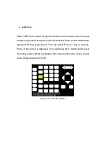


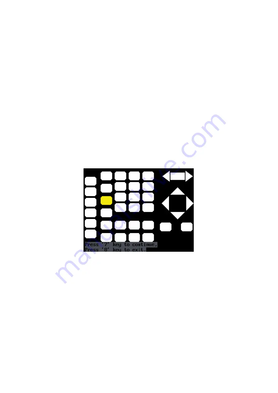
3. LED Test
Select ‘LED Test’ to enter the lighten interface, the on-screen lathy rectangle
shapes represent the front panel keys; the shapes with two arrows beside them
represent the front panel knobs. The clew words ‘Press ‘7’ Key to continue,
‘Press ‘8’ Key to exit’ is displayed, You could press the ‘7’ button continuously
for testing, when buttons are lighted ,the corresponding area on the screen
would display green(color LCD).
Figure 2- 74 Led Test Interface
Summary of Contents for SFG-20 Series
Page 1: ...5 10 MHz Arbitrary Function Waveform Generators User Manual SFG 20X ...
Page 30: ...Figure 2 5 Setting the Offset ...
Page 40: ...Figure 2 15 Setting the Rise edge ...
Page 94: ...Figure 3 1 Sine Waveform ...
Page 96: ...Figure 3 2 Square Waveform ...
Page 103: ...the wave generated is shown in Figure 3 6 Figure 3 6 Sinc Waveform ...
Page 109: ...Figure 3 9 AM Waveform ...
Page 111: ...10 Figure 3 10 FM Waveform ...
Page 113: ...Figure 3 11 PM Waveform ...
Page 115: ...Figure 3 12 FSK Waveform ...
Page 117: ...Figure 3 13 ASK Waveform ...
Page 119: ...14 Figure 3 14 PWM Waveform ...
Page 121: ...Figure 3 15 DSB AM Waveform ...


