


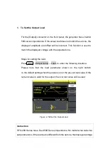


will not equal the real voltage.
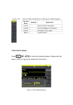
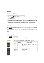
2. To Set the Invert Waveform
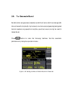
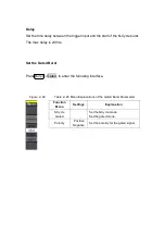
Press Utility
→
Output Setup
→
Invert, to set the Inverse Waveform Output.
When the waveform is inverse, no offset will change.
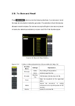
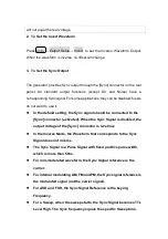
3. To Set the Sync Output
The generator provides Sync output through the [Sync] connector on the rear
panel. All standard output functions (except DC and Noise) have a
corresponding Sync signal. For some applications, they can be disabled if users
do not want to use it,
In the default setting, the Sync signal should be connected to the
!
[Sync] connector (activated). When the Sync Signal is disabled, the
output voltage of the [Sync] connector is level low.
In the Inverse Mode, the Waveform that corresponds to the Sync
!
Signal does not inverse.
The Sync Signal is a Pulse Signal with fixed positive pulse width,
!
which is more than 50ns.
For non-modulated waveform, the Sync Signal reference is the
!
carrier.
For internal modulating AM, FM and PM, the Sync signal reference is
!
the modulated signal (not the carrier signal).
For ASK and FSK, the Sync Signal Reference is the keying
!
Frequency.
For a Sweep, when the sweep starts, the Sync Signal becomes TTL
!
Level High. The Sync frequency equals the specific Sweep time.
Summary of Contents for SFG-20 Series
Page 1: ...5 10 MHz Arbitrary Function Waveform Generators User Manual SFG 20X ...
Page 30: ...Figure 2 5 Setting the Offset ...
Page 40: ...Figure 2 15 Setting the Rise edge ...
Page 94: ...Figure 3 1 Sine Waveform ...
Page 96: ...Figure 3 2 Square Waveform ...
Page 103: ...the wave generated is shown in Figure 3 6 Figure 3 6 Sinc Waveform ...
Page 109: ...Figure 3 9 AM Waveform ...
Page 111: ...10 Figure 3 10 FM Waveform ...
Page 113: ...Figure 3 11 PM Waveform ...
Page 115: ...Figure 3 12 FSK Waveform ...
Page 117: ...Figure 3 13 ASK Waveform ...
Page 119: ...14 Figure 3 14 PWM Waveform ...
Page 121: ...Figure 3 15 DSB AM Waveform ...


