background image

Automation
Section 3  The AutoSampler Module

3-14

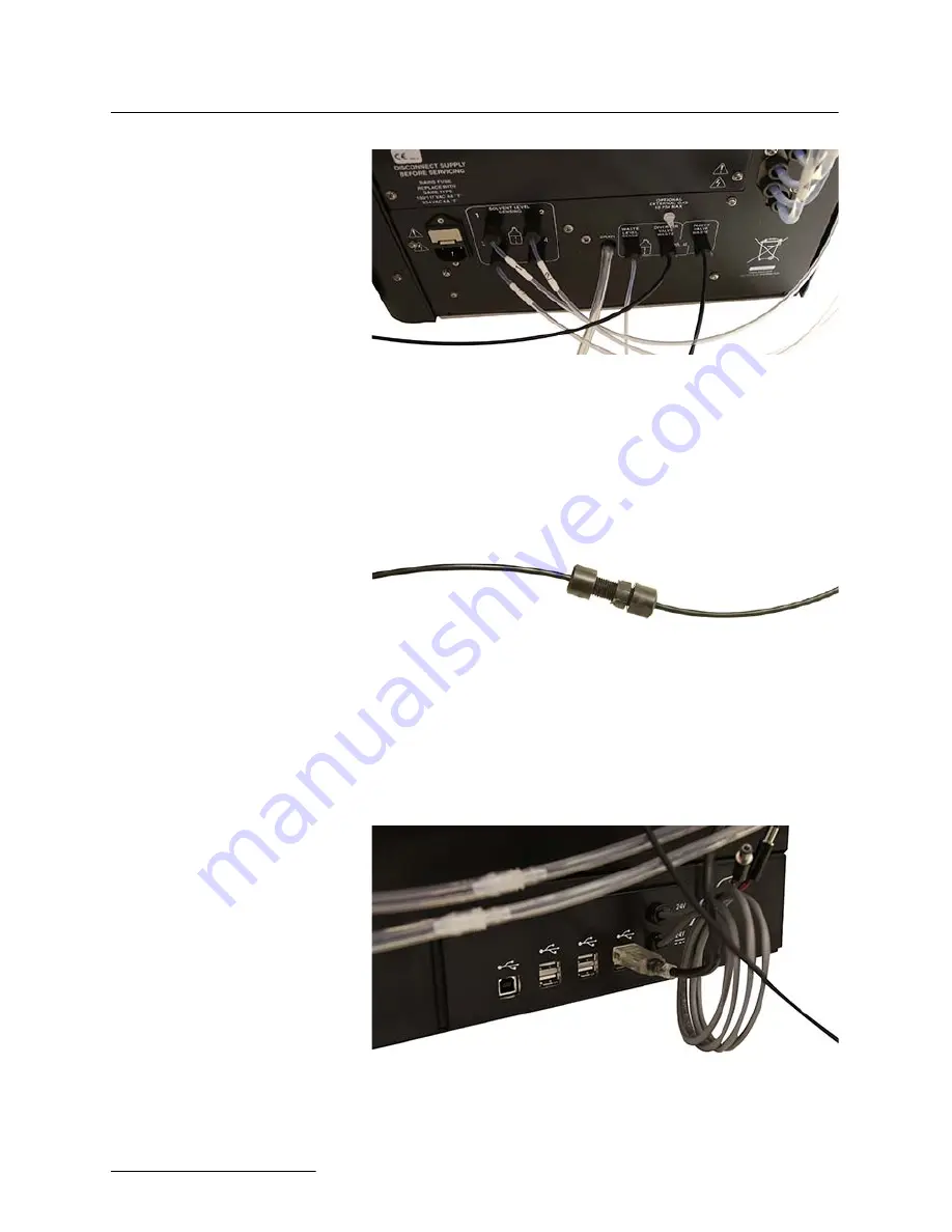
Figure 3-24 Diverter Valve Waste port with AutoSampler 

Module tubing connection

13. Connect the remaining tubing from the AutoSampler to 

the tubing removed in Step 11.

Figure 3-25 Connecting AutoSampler waste tubing to EZ 

Prep waste tubing

14. Connect the USB-A cable attached to the AutoInjector 

Module to one of the USB-A ports located on the back of 
the AutoSampler Module.

Figure 3-26 AutoSampler Module USB-A connection

Summary of Contents for AutoInjector Module

Page 1: ...Automation Modules Installation and Operation Guide 69 5233 772 Copyright 2016 Teledyne Technologies Incorporated All rights reserved Released July 2016 ...

Page 2: ......

Page 3: ...n provided by the instrument may be impaired WARNING WARNING If you are using flammable solvents or chemicals with this system vapor concentration levels may exceed the maximum exposure levels as recommended by OSHA Guide 1910 1000 To reduce those levels to a safe exposure Teledyne Isco recommends that you place the system in a laboratory hood designed for the purpose of ventilation This hood shou...

Page 4: ...thin the trian gle is a warning sign alerting you of dangerous voltage inside the product Symboles de sécurité Ce symbole signale l existence d instructions importantes relatives au produit dans ce manuel Ce symbole signale la présence d un danger d électocution Warnungen und Vorsichtshinweise Das Ausrufezeichen in Dreieck ist ein Warn zeichen das Sie darauf aufmerksam macht daß wichtige Anleitung...

Page 5: ...ety Warnings 5 For Additional Information Technical assistance for the Teledyne Isco Automation Modules can be obtained from Teledyne Isco 4700 Superior St Lincoln NE 68504 Phone 800 775 2965 or 402 464 0231 Fax 402 465 3001 E mail IscoService teledyne com ...

Page 6: ...Automation Modules Installation and Operation Guide Safety Warnings 6 ...

Page 7: ...ler Module Operation 3 20 3 3 1 Setup 3 20 3 3 2 Operation 3 21 Section 4 The Column Selector Module 4 1 Column Selector Module Installation 4 1 4 1 1 Installing the Column Selector Module 4 1 4 1 2 Establishing Column Selector Module Connections 4 6 4 1 3 Mounting the AutoInjector Module to the Column Selector Module 4 8 4 1 4 Establishing AutoInjector Module Connections 4 16 4 2 Installing the C...

Page 8: ...Automation Modules Table of Contents 8 ...

Page 9: ...utoSampler Module performs automated purifications on multiple samples In addition the module doubles the fraction collection capacity of the EZ Prep by adding two collection racks For more flexibility samples can consist of multiple injections You can even choose between maximizing rack capacity by filling racks completely or optimizing work flow on a shared system by having each sample sent to t...

Page 10: ...Automation Modules Section 1 Introduction 1 2 ...

Page 11: ...dule the standard prep column mount can be removed to keep the overall system width minimized In this case the AutoInjector Module can be mounted on top of the Column Selector Module instead of on top of the standard prep column mount Installation 1 Turn off the EZ Prep 2 Remove the top cover of the EZ Prep column mount by grasping and pulling straight up Figure 2 1 Removing the top cover of the E...

Page 12: ...emove the check valve from this line and set it aside for later use Discard the waste line Figure 2 3 Removing the waste line from the EZ Prep inject valve 5 Install the AutoInjector Module by placing it on top of the prep column mount and pressing downwards The tab on the bottom of the AutoInjector Module will snap into the receptacle on the top of the prep column mount ...

Page 13: ...es 7 Connect the included power supply from the AutoInjector Module to a suitable power connection Use a power supply in a location that minimizes the possibility of a chemical spill damaging the power supply 8 Locate the supplied waste tubing and fitting package P N 60 5234 653 9 Unscrew the attached plastic ferrule in this fitting package until the plastic ferrule is almost completely detached f...

Page 14: ...ght to the valve 12 Turn the steel fitting 1 2 turn tighter 13 Remove the plastic ferrule while leaving the fitting attached Figure 2 6 Waste fitting with the plastic ferrule removed 14 Attach the supplied tubing from this package to the secured fitting Tighten the ferrule finger tight with the supplied tool Ensure the tubing and fitting are snug in the EZ Prep inject valve ...

Page 15: ...ed 15 Connect the opposite end of this tubing to the left port of the AutoInjector Module Figure 2 8 Connection of the waste tubing from the EZ Prep inject valve to the left AutoInjector Module port 16 Connect the supplied waste line P N 60 5234 654 to the right port of the AutoInjector Module ...

Page 16: ...he AutoInjector Mod ule as shown in Figure 2 10 Figure 2 10Check valve connected to the waste line of the AutoInjector Module 18 Locate the supplied sample probe tubing and fitting pack age P N 60 5234 657 19 Unscrew the attached plastic ferrule in this fitting package until the plastic ferrule is almost completely detached from the steel fitting 20 Attach the steel fitting in this package to the ...

Page 17: ... tight to the valve 22 Turn the steel fitting 1 2 turn tighter 23 Remove the plastic ferrule while leaving the fitting attached Figure 2 12Sample tube fitting with the plastic ferrule removed 24 Attach the supplied tubing from this package to the secured fitting by screwing the new plastic ferrule into the fitting Tighten the ferrule finger tight with the supplied tool ...

Page 18: ...e samples The software will display a warning if the system is programmed to fill the loop to more than 50 of total volume This warning can be ignored at the discretion of the user 2 2 AutoInjector Module Operation 2 2 1 Setup Before using the AutoInjector Module for the first time the EZ Prep should be configured for the proper injection loop volume 1 Begin by going to TOOLS CONFIG PREP HPLC 2 Se...

Page 19: ...w the steps below 1 Place the sample probe into your sample container 2 Press PLAY to start a separation as you would for an indi vidual separation 3 If you want to automatically perform multiple injections or perform a single injection using the AutoInjector Mod ule select the Multiple Injections drop down as shown in Figure 2 15 This is the default selection if an AutoInjector Module is present ...

Page 20: ...njector Module 2 10 Figure 2 15Selecting for multiple injections 5 In the dialogue box enter the total sample volume and the number of injections as show in Figure 2 16 Figure 2 16Selecting the sample volume and number of injections ...

Page 21: ...ffect the overall run length 6 After the last injection is performed a sample probe wash screen is shown prompting the user to wash the probe with a strong solvent followed by a weak solvent Perform these duties as requested Note A weak solvent is used following the usage of the strong sol vent to inhibit poor separation due to excessive strong solvent in the probe tubing It is important to perfor...

Page 22: ...y viewed by pressing the left or right arrows at the lower left and right of the file viewer screen Figure 2 17 This function can also be used to immediately view files before or after the currently viewed file even if they are not part of the same injection sequence Figure 2 17Viewing injections ...

Page 23: ...ll be prompted to place the AutoSam pler Module on the right side of the EZ Prep in 3 1 2 Estab lishing Connections The AutoSampler Module includes the AutoInjector Module to perform its automated functions To install the AutoSampler Module follow the steps below 3 1 1 Installing the AutoSampler Module 1 Mount the rinse station by placing it into the receptacle located on the right rear portion of...

Page 24: ...ed 3 at the bottom of the AutoSampler Module s peristaltic pump Be sure to select the fitting furthest from the back of the mod ule Figure 3 3 Routing the bottom section of wash station tubing 3 Route the top section of tubing labeled 2 from the rinse station to the matching fitting labeled 2 at the top of the AutoSampler Module s peristaltic pump Be sure to select the fitting closest to the back ...

Page 25: ...put tubing section assembly 5 Attach the assembled wash solution input tubing sections to the remaining fittings on the peristaltic pump These tubing sections are labeled 1 and 4 and are attached to the respectively labeled fittings The free ends will be inserted into the wash solution container Note Alternatively to Step 5 the free end of the tubing section labeled 4 can be connected to a waste c...

Page 26: ...nto the wash solution be sure only the smaller piece of tubing is resting inside the solution 6 Carefully unpack the Z Drive 7 Find the Y axis carriage on the arm of the AutoSampler Module The Z Drive will be attached to this carriage Figure 3 6 Column Selector Module Y axis arm 8 Slide the Z Drive onto the arm until the two holes align with the matching holes in the Y axis carriage ...

Page 27: ...7 Z Drive mounted on the Y axis carriage 9 Secure the Z Drive to the carriage using the two thumb screws Tighten the thumbscrews with your fingers Figure 3 8 Z Drive secured to the Y axis carriage 10 Insert the two loosened probe clamps into the Z axis slider ...

Page 28: ...10Probe inserted into the Z axis slider 12 Move the Z Drive to the topmost position on the Z axis 13 Guide the probe down until the tip of the probe is level with the bottom of the Z Drive and then tighten the probe clamps with your hands Mounting the AutoInjector Module 14 Install the AutoInjector Module onto the AutoSampler Module by removing the upper left and lower right mount ing screws on th...

Page 29: ...removed 15 Place the AutoInjector Module on top of the AutoSampler Module and fasten them together with the mounting screws removed in Step 14 Figure 3 12AutoInjector Module fastened to the AutoSampler Module 16 Feed all cables with the exception of the sample probe tub ing through the rear guide block of the AutoInjector Mod ule ...

Page 30: ...rive 17 Turn the rotor on the back of the AutoSampler Module clockwise as far as it will go 18 Slide the green probe cable through the rear guide block and into the rotor until it completes the route Tighten the nut to secure the probe cable sleeve to the rear guide block Figure 3 14Route of the probe cable through the rotor ...

Page 31: ...ve as shown in Figure 3 15 Figure 3 15Illustration of the proper probe cable route through the rotor 19 Loosen the thumbscrew on the rotor to allow the cable to pass through the clamp Extend about 2 mm of cable past the clamp 20 Verify that there is a small gap approx 1 3 mm between the Z axis slider and the cap at the top of the Z Drive Adjust the cable as necessary ...

Page 32: ...ble by tightening the thumbscrew on the rotor The thumb screw should be as tight as possible using just your fingers Figure 3 17Probe cable secured onto the rotor 22 Rotate the Z Drive rotor back and forth to ensure that the Z Drive moves up and down freely Note If the rotor does not move freely check that the other cables are not interfering with the movement of the green probe cable ...

Page 33: ...e the supplied sample probe tubing and fitting pack age P N 60 5234 651 4 Unscrew the attached plastic ferrule in this fitting package until the plastic ferrule is almost completely detached from the steel fitting 5 Attach the steel fitting in this package to the EZ Prep inject valve waste port This steel fitting should be hand tight Figure 3 19Sample probe tube fitting connected to the EZ Prep in...

Page 34: ...kage to the secured fitting by screwing the new plastic ferrule into the fitting Tighten the ferrule finger tight with the supplied tool Note The spring attached to the tubing prevents kinks from develop ing in the tubing Figure 3 21Sample probe tube fitting with sample probe tubing attached 10 Secure the probe tubing to the side of the EZ Prep by removing the housing screw fitting the tubing brac...

Page 35: ...eads vertically through the bracket This ensures that the probe tubing will not be obstructed by other tubing 11 Disconnect the tubing at the back of the EZ Prep from the port labeled DIVERTER VALVE WASTE Figure 3 23Diverter Valve Waste port with no connection 12 Connect the compatible tubing from the AutoSampler Module to the port labeled DIVERTER VALVE WASTE at the back of the EZ Prep ...

Page 36: ...onnect the remaining tubing from the AutoSampler to the tubing removed in Step 11 Figure 3 25Connecting AutoSampler waste tubing to EZ Prep waste tubing 14 Connect the USB A cable attached to the AutoInjector Module to one of the USB A ports located on the back of the AutoSampler Module Figure 3 26AutoSampler Module USB A connection ...

Page 37: ... the USB B port on the back of the AutoSampler Module Figure 3 27EZ Prep USB A connection Figure 3 28AutoSampler Module USB B connection 16 Connect the second provided USB cable from the USB B port on the back of the AutoSampler module to one of the USB A ports on the back of the module Figure 3 29AutoSampler Module USB B connection ...

Page 38: ...mpler Module USB A connection center 17 Connect the Z Drive power cable to the port on the back of the AutoSampler Module Figure 3 31Z Drive power cable connected to the AutoSampler Module 18 Locate the AutoSampler Module s power supply bracket as show in Figure 3 32 ...

Page 39: ... 3 The AutoSampler Module 3 17 Figure 3 32AutoSampler Module power supply bracket 19 Remove the two bottom screws from the AutoSampler Module s rotor Figure 3 33AutoSampler Module rotor before removing the bottom screws ...

Page 40: ...r the bottom screws 20 Place the power supply bracket so the two holes in the bracket align with the two holes on the AutoSampler Mod ule s rotor Secure the bracket with the provided screws Figure 3 35Power supply bracket secured to the AutoSampler Module 21 Slide the power supply into the bracket ...

Page 41: ...er supply to a suitable power source Figure 3 37AutoSampler Module with power connection made 3 2 Installing the AutoSampler Module with the Column Selector Module Using the AutoSampler Module in conjunction with the Column Selector Module does not affect the installation process for either module Please install each module in accordance with the instructions given in that module s section ...

Page 42: ... the new rack will be made available for use The sample racks also have RFID tags which allow for the recognition of vial locations Note The sample rack cannot be swapped during a separation sequence 3 3 1 Setup Before using the AutoSampler Module for the first time the EZ Prep should be configured for the proper injection loop volume 1 Begin by going to TOOLS CONFIG PREP HPLC 2 Select the loop vo...

Page 43: ...Sampler Module you will need to create a sample queue After the AutoSampler Module has been installed and the EZ Prep is in the PREP HPLC mode the software will display two tabs at the bottom of the screen Accessing the RUN tab will result in a screen and oper ation much like the standard EZ Prep without an installed AutoSampler Module Pressing PLAY will display the RUN REQUIREMENTS screen On this...

Page 44: ...method name and a list of methods associated with the column will appear These methods will be listed in the order they were created Alternatively select CUSTOMIZE CURRENT METHOD or BROWSE to populate this field Select CUSTOMIZE CURRENT METHOD to create a modified version of the method for use in the current queue To use this modified method exit the method editor and select SAVE when prompted A n...

Page 45: ... separation To easily view previous separations select the separation on the QUEUE screen or select FILE OPEN to view previous separations If a sample had multiple injections the run sequence will be dis played within the FILE OPEN dialogue under a single name pre ceded by a symbol This symbol indicates there are multiple injections with the same base file name Names are appended with I to signify...

Page 46: ...Automation Section 3 The AutoSampler Module 3 24 ...

Page 47: ...dule horizontally it is recommended that you install the columns prior to continuing with the Column Selector Module installation is recommended If you are installing the module vertically install the columns after installing the module 4 1 1 Installing the Column Selector Module To install the Column Selector Module vertically please follow the steps below Removing the housing from the EZ Prep 1 ...

Page 48: ...nch to remove the nut located inside the EZ Prep column housing Figure 4 3 Removing the EZ Prep housing column inner nut 4 Use a screwdriver to remove the two screws from the back of the housing The housing will come free from the EZ Prep at this time with little effort 5 Remove the mounting rail from the right side of the EZ Prep by removing the two nuts from the mounting rail using a 5 16 wrench...

Page 49: ...nting rail securing nuts Mounting the Column Selector Module 1 Remove the three thumbscrews from the housing of the Column Selector Module by hand Figure 4 5 Location of the three Column Selector Module housing thumbscrews 2 Separate the housing of the Column Selector Module using little effort ...

Page 50: ...Remove these two screws with a screwdriver Figure 4 6 Two screws on top of the Column Selector Modules 4 Remove the cover plate and set it aside 5 Insert the mounting rail attachment into the designated slot located on top of the Column Selector Module and secure it to the module with the attached screw Figure 4 7 Column Selector Module with mounting rail attachment configured ...

Page 51: ...ting rail attach ment to the EZ Prep using the provided thumbscrew Figure 4 8 Location of the Column Selector Module mounting rail attachment thumbscrew 8 Use the provided thumbscrew and washer to attach the Column Selector to the EZ Prep at the bottom of the mod ule Figure 4 9 Location of the Column Selector Module lower attachment thumbscrew ...

Page 52: ... connects the EZ Prep inject valve to the column inlet 3 Connect one end of the provided stainless steel tubing to the EZ Prep inject valve 4 Connect the other end of the provided stainless steel tub ing to the inlet port located on the back of the Column Selector Module Figure 4 11Column Selector Module inlet port 5 Cut a piece of the provided green PEEK tubing which is long enough to reach from ...

Page 53: ...uration Figure 4 13Connected Column Selector Module outlet port tubing Note For instructions on assembling the tubing connections please see the instruction sheet included with the hardware The Column Selector Module has multiple channels for retaining the column mounting clamps To change the channels simply unscrew the retainer at the end of the track slide the column mounting clamp off the track...

Page 54: ...ation during your initial configuration After the configu ration is complete the columns will be selected by name rather than by how they are connected 10 If desired secure the housing of the Column Selector Mod ule back onto the module using the thumbscrews removed in Step 1 of Removing the housing from the EZ Prep 11 Connect the power supply from the Column Selector Mod ule to a power source 4 1...

Page 55: ...ed with the module Figure 4 15Column Selector Module with attached AutoInjector Module 3 Remove the Luer fitting from the EZ Prep inject valve Figure 4 16Removing the Luer fitting from the EZ Prep inject valve 4 Remove the waste line from the EZ Prep inject valve Remove the check valve from this line and set it aside for later use Discard the waste line ...

Page 56: ...l snap into the receptacle on the top of the prep column mount Figure 4 18AutoInjector Module attached to the EZ Prep column mount 6 Connect the USB cable from the AutoInjector Module to the USB port on the rear of the EZ Prep If you have a CombiFlash Rf PurIonTM Mass Detector attached to the EZ Prep you will need to obtain a USB hub to connect both modules 7 Connect the included power supply from...

Page 57: ...tting package until the plastic ferrule is almost completely detached from the steel fitting 10 Attach the steel fitting in this package to the EZ Prep inject valve waste port This steel fitting should be hand tight Figure 4 19Waste tubing fitting attached to the EZ Prep inject valve 11 Turn the plastic ferrule until it is attached hand tight to the valve 12 Turn the steel fitting 1 2 turn tighter...

Page 58: ...ch the supplied tubing from this package to the secured fitting Tighten the ferrule finger tight with the supplied tool Ensure the tubing and fitting are snug in the EZ Prep inject valve Figure 4 21Waste fitting with tubing attached 15 Connect the opposite end of this tubing to the left port of the AutoInjector Module ...

Page 59: ...16 Connect the supplied waste line P N 60 5234 654 to the right port of the AutoInjector Module Figure 4 23Waste line connected to the right AutoInjector Module port 17 Connect the check valve removed in Step 4 to the waste line from the AutoInjector Module Ensure that the arrow on the check valve points away from the AutoInjector Mod ule as shown in Figure 4 24 ...

Page 60: ...ting package until the plastic ferrule is almost completely detached from the steel fitting 20 Attach the steel fitting in this package to the EZ Prep inject valve waste port This steel fitting should be hand tight Figure 4 25Sample tube fitting attached to the EZ Prep inject valve 21 Turn the plastic ferrule until it is attached hand tight to the valve 22 Turn the steel fitting 1 2 turn tighter 2...

Page 61: ... Attach the supplied tubing from this package to the secured fitting by screwing the new plastic ferrule into the fitting Tighten the ferrule finger tight with the supplied tool Note The spring attached to the tubing prevents kinks from develop ing in the tubing Figure 4 27Sample tube fitting with sample tubing attached ...

Page 62: ...le does not affect the installation process for either module Please install each module in accordance with the instructions given in that module s section 4 3 Column Selector Module Operation 4 3 1 Setup Before using the Column Selector Module for the first time the CombiFlash EZ Prep must be configured to identify the column in each position Once the columns have been installed in the Column Sel...

Page 63: ...able the debubbler without having one of these words present 4 To set other method parameters as default for the column being defined or to create a new method with custom parameters use the DEFINE METHODS button 5 Once the column definition is set press the SAVE button 6 To identify the column in each position select the drop down menu in upper portion of the screen and choose a previously define...

Page 64: ...Automation Section 4 The Column Selector Module 4 18 ...

Page 65: ... 3 inches 12 7 x 4 8 x 16 0 cm Weight 4 lb 1 8 kg Temperature 20 40 C Maximum Humidity 95 relative humidity Input Voltage 100 240 VAC 50 60 Hz Amps 2 Disconnect Device Line cord Electrical Safety per EN 61010 1 Pollution Degree 2 Installation Category II Maximum Altitude 2 000 m Sample Size 0 1 mL minimum ...

Page 66: ...3 inches 48 0 x 35 6 x 49 0 cm Weight 31 lbs 14 1 kg Temperature 20 40 C Maximum Humidity 95 relative humidity Input Voltage 100 240 VAC 50 60 Hz Amps 2 Disconnect Device Line cord Electrical Safety per EN 61010 1 Pollution Degree 2 Installation Category II Maximum Altitude 2 000 m Sample Size 0 1 mL minimum ...

Page 67: ... 11 7 x 40 9 cm Dimensions horizontal setup 4 6 x 14 5 x 16 1inches 11 7 x 36 8 x 40 9 cm Weight 12 9 lb 5 9 kg Temperature 20 40 C Maximum Humidity 95 relative humidity Input Voltage 100 240 VAC 50 60 Hz Amps 2 Disconnect Device Line cord Electrical Safety per EN 61010 1 Pollution Degree 2 Installation Category II Maximum Altitude 2 000 m ...

Page 68: ...Automation Appendix A Specifications A 4 ...

Page 69: ...Compliance Statements C E D e c l a r a t i o n o f C o n f o r m i t y P e n d i n g ...

Page 70: ......

Page 71: ... 摞 ST 㪖 屓 䤓棟摞尐㻑ⅴₚᇭ O Represent the concentration of the hazardous substance in this component s any homogeneous pieces is lower than the ST standard limitation X 嫷䯉年㦘㹡㦘 䓸德咂 年捷ↅ䤓㩟 德㧟㠨 䤓 摞怔 ST 㪖 屓 䤓棟摞尐㻑ᇭ 㷳 㫈㗽 棔 ₙ嫷 㓢 X 䤓㔏㦾 扪嫛扪 㷴広㢝ᇭ X Represent the concentration of the hazardous substance in this component s at least one homogeneous piece is higher than the ST standard limitation Manufacturer may give...

Page 72: ......

Page 73: ...ue to corrosion misuse accident or lack of proper LQVWDOODWLRQ RU maintenance This warranty does not cover products not sold under the Teledyne Isco trademark or for which any other warranty is specifically stated No item may be returned for warranty service without a return authorization number RMA issued by Teledyne Isco This warranty is expressly in lieu of all otherwarranties and obligations a...

Page 74: ......

Reviews: