M-412-073 Chapter 3: Installation Instructions
TELEDYNE TAPTONE
10
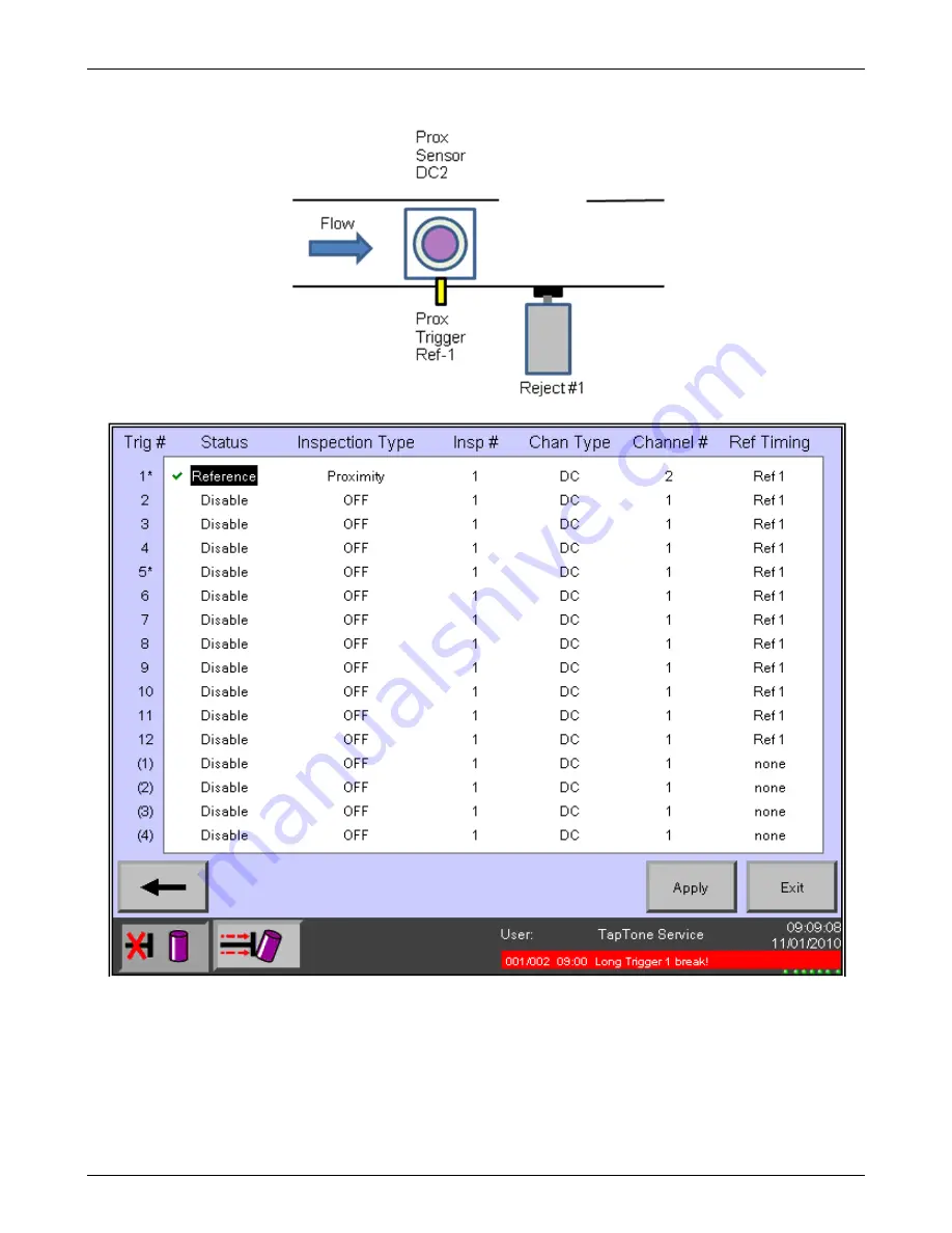
3.1.3 Proximity Configuration (T4000 P)
Page 1: ...TapTone T4000 APX Installation Manual M 412 073 Rev B...
Page 2: ...This page left blank...
Page 3: ...TapTone T4000 APX Installation Manual M 412 073 Rev B English TELEDYNE TAPTONE 49 Edgerton Drive North Falmouth Massachusetts 02556 2828 USA Phone 508 563 1000 Fax 508 564 9945 www taptone com...
Page 4: ...This page left blank...
Page 5: ...5 X ray Configuration T4000 X 12 3 1 6 Acoustic X ray Configuration T4000 AX 13 3 1 7 Proximity X ray Configuration T4000 PX 14 3 1 8 Acoustic Cocked Crown X ray Configuration T4000 ACX 15 3 1 9 Acou...
Page 6: ...ic Control Box Specifications 43 B 2 Fill_xr Sensor Specifications 44 Appendix C X Ray Safety Survey Plot B 412 119 45 Reference Manuals M 412 102 TapTone T4000 Operations Manual English M 412 073 Tap...
Page 7: ...ector Mask 24 Figure 3 8 Rejector Specifications 25 Figure 3 9 Rejector Assembly Adjustment Points 26 Figure 3 10 Rejector Regulator Lubricator Mounting 27 Figure 3 11 Rejector Regulator Lubricator Ai...
Page 8: ...oor stand for easy mounting 12 of travel for height adjustment Digital indicator for accurate change over Fill_xr X ray Features include Underfill and Overfill inspections with one head Angled or stra...
Page 9: ...or height adjustment Digital indicator for accurate change over Fill_xr Features include Underfill and Overfill inspections with one head Angled or straight control box Stainless steel design Digital...
Page 10: ...with a 4 5 meter 15 ft quick disconnect water proof cable The X ray lamp on sensor indicates when the X ray module is transmitting Fill_xr Features include Underfill and Overfill inspections with one...
Page 11: ...the enclosure Do not disconnect any electrical connections when the system power is on Damage to electrical components may occur Use lockout tag out equipment to prevent injury or damage when servicin...
Page 12: ...n operation Do not operate this equipment with long hair or baggy loose clothing Serious injury may occur if it gets caught in any moving parts WARNING Keep hands clear of X ray tunnel when X ray lamp...
Page 13: ...M 412 073 Chapter 2 Safety Precautions TELEDYNE TAPTONE 6 Denotes X ray lamp Standard CE Figure 2 2 X ray Safety Labels Indicates X ray caution and emission direction...
Page 14: ...ystem main power switch to the OFF 0 position for both the inspection electronics enclosure and the compression belt motor control enclosure 2 Place a pad lock through one of the three switch lock loo...
Page 15: ...M 412 073 Chapter 3 Installation Instructions TELEDYNE TAPTONE 8 3 0 Installation Instructions 3 1 T4000 Sensor Configurations 3 1 1 Acoustic Configuration T4000 A...
Page 16: ...3 Installation Instructions TELEDYNE TAPTONE 9 3 1 2 Acoustic Cocked Crown Configuration T4000 AC Acoustic Sensor AC 1 Cocked Crown Sensor DC 4 Flow Acoustic Trigger Trig 1 Ref 1 Cocked Crown Trigger...
Page 17: ...M 412 073 Chapter 3 Installation Instructions TELEDYNE TAPTONE 10 3 1 3 Proximity Configuration T4000 P...
Page 18: ...2 073 Chapter 3 Installation Instructions TELEDYNE TAPTONE 11 3 1 4 Dual Proximity Configuration T4000 DP Prox Sensor DC 2 Prox Sensor DC 4 Flow Prox 1 Trigger Trig 1 Ref 1 Prox 2 Trigger Trig 7 Rejec...
Page 19: ...M 412 073 Chapter 3 Installation Instructions TELEDYNE TAPTONE 12 3 1 5 X ray Configuration T4000 X...
Page 20: ...M 412 073 Chapter 3 Installation Instructions TELEDYNE TAPTONE 13 3 1 6 Acoustic X ray Configuration T4000 AX...
Page 21: ...M 412 073 Chapter 3 Installation Instructions TELEDYNE TAPTONE 14 3 1 7 Proximity X ray Configuration T4000 PX...
Page 22: ...tions TELEDYNE TAPTONE 15 3 1 8 Acoustic Cocked Crown X ray Configuration T4000 ACX Acoustic Sensor AC 1 Cocked Crown Sensor DC 4 Flow Acoustic Trigger Trig 1 Ref 1 Cocked Crown Trigger Trig 7 Reject...
Page 23: ...n Instructions TELEDYNE TAPTONE 16 3 1 9 Acoustic Proximity X ray Configuration T4000 APX Acoustic Sensor AC 1 Prox Sensor DC 4 Flow Acoustic Trigger Trig 1 Ref 1 Prox Trigger Trig 7 Reject 1 X ray Se...
Page 24: ...ails must be straight and guide the containers smoothly through the inspection head The location should allow the rejector to be mounted on the conveyor with an adequate size collection bin 2 The tran...
Page 25: ...base by loosening the 4 bolts 7 Mark and cut the bottom of the stand tube by the length calculated CUTOFF 8 Reassemble the tripod base to the stand by tightening the 4 bolts 9 Reassemble the junction...
Page 26: ...orking components of the conveyor 3 Drill four 11 32 8 73mm diameter holes on each side of the conveyor for the frame mounting bolts 4 Install the frame assembly using the hardware listed below For co...
Page 27: ...ation Instructions TELEDYNE TAPTONE 20 8 Mount the junction box using the 20 x hardware provided 9 Connect the sensor cables according to the junction box cable diagram Figure 3 3 Figure 3 3 Conveyor...
Page 28: ...e product contents time to settle before fill height measurement For accurate measurement the conveyor flow should be as smooth as possible The X ray tunnel must be level with the conveyor deck The fl...
Page 29: ...M 412 073 Chapter 3 Installation Instructions TELEDYNE TAPTONE 22 3 3 3 Stand Assembly Procedure Figure 3 5 X ray Mechanical Assembly Diagram...
Page 30: ...o the maximum height for ease in lifting the unit over the conveyor 3 Center the container flow within the X ray tunnel 4 Level the system to the conveyor with the stand leveling pads 5 Bolt system fe...
Page 31: ...7 6 mm x 12 7 mm Detector Mask Installation The fill height detection range is 12 7 mm 1 2 in These masks are used when the space between the top of the product and the container lid is small or when...
Page 32: ...Specifications Stroke 12 7 mm or 25 4 mm 1 2in or 1in Construction Stainless steel conveyor mounted Wash Down High pressure water Regulator Assembly Filter Regulator Lubricator module with lockout Rej...
Page 33: ...ster line speeds the conveyor cut away must be larger as shown in figure x x Line Speed bottles min Guide Rail Opening 000 749 3 x Can Diameter Minimum 750 1249 5 x Can Diameter Minimum 1250 2000 8 x...
Page 34: ...the rejector regulator lubricator to the conveyor side wall next to the rejector in a location that allows it to be easily serviceable 2 Fill the bowl of the lubricator with 5 weight petroleum based o...
Page 35: ...bar 150 psi 2 Connect the shop air supply to the input side of the regulator assembly supplied with the system 3 Turn air supply ON and set the pressure of the regulator to a reading of approximately...
Page 36: ...on Instructions TELEDYNE TAPTONE 29 3 4 4 Rejector Electrical Connection 1 Connect the 4 pin yellow rejector plug into the rejector 1 socket located in the bottom Left side of the junction box Figure...
Page 37: ...tions CAUTION Excessive side loads to the shaft will damage the encoder and could lead to premature failure Make sure the shafts line up and the coupling between them is flexible Figure 3 14 Shaft Enc...
Page 38: ...mounted to The encoder shaft is 9 5mm 3 8 diameter 3 Each mounting location is different so a custom designed bracket will need to be designed Fabricate a bracket to mount the shaft encoder over the c...
Page 39: ...cal Connections STEPS 1 Connect the shaft encoder female plug into the socket on the shaft encoder Make sure the connector is tight to prevent water intrusion 2 Note the electrical wiring diagram for...
Page 40: ...ements 100 120VAC OR 200 240VAC 1 Phase 3 0Amps 275Watts 1 Set the 24V power supply ac input power selector switch to the appropriate setting based on you AC power source This supply is located in the...
Page 41: ...BRN 16 BLU 16 013210 CABLE A BRN 16 BLU 16 011830 GRN YEL 14 TO DOOR GND STUD GRN YEL 14 Lower Lef t Box Stud BOX STUD PE GRN YEL 14 BLU 14 neutral BRN 14 line Switched AC Power Conduit 1 BLACK Denote...
Page 42: ...ons TELEDYNE TAPTONE 35 3 6 2 Sensor Cable Connections PROXIMITY or COCKED CROWN SENSORS Figure 3 19 Proximity Head Cable Connections ACOUSTIC SENSOR Figure 3 20 Acoustic Head Cable Connections Microp...
Page 43: ...LEDYNE TAPTONE 36 X RAY SENSOR 1 Connect the X ray power cable to the large socket on the bottom of the control box 2 Connect the X ray trigger sensor to the photo beam module Figure 3 21 X ray Head C...
Page 44: ...or first when using the combination acoustic cocked crown kit 2 Adjust the conveyor rails to the container for a gap of 1 8 3mm maximum The containers should pass smoothly through the inspection head...
Page 45: ...n either side of the container Containers should pass smoothly through the X ray tunnel 2 Adjust the height of the X ray sensor with the crank handle on the top of the stand Set the X ray sensor heigh...
Page 46: ...that will identify a missed reject Select reject acknowledge function for the desired PLC output When the output is activated press the ENTER key to clear the alarm condition 3 7 6 Trigger Sensor Set...
Page 47: ...ion sensors to initiate proper timing input function 2 Go to the Trigger Setup screen as shown below 3 The Trigger Setup screen will show the Inspection Triggers that are activated with green check ma...
Page 48: ...s turned off This procedure DOES NOT need to be done ever again unless you add new inspection sensors 6 Trigger sensor programming is now complete press Exit to return to the system home screen This p...
Page 49: ...NESS FOR A PARTICULAR PURPOSE IS INTENDED OR GIVEN IN THE CASE OF GOODS OTHER THAN THOSE OF TELEDYNE TAPTONE S OWN MANUFACTURE TELEDYNE TAPTONE MAKES NO WARRANTIES EXPRESS STATUTORY OR IMPLIED LIMITAT...
Page 50: ...Wash Down Low pressure water Mounting Angled pedestal stand stainless steel HMI Watertight LCD touch screen 25 4 cm 10 in Reject Lamp 24 VDC 6 5 watt orange lens 1 2 second pulse per reject Reject Si...
Page 51: ...estal stand to floor secured to conveyor STAND Type Adjustable height Travel Range Crank handle fine adjust 304 8 mm 12 in Overall floor to X ray beam range does not include fine adjust range standard...
Page 52: ...M 412 073 Appendix C X Ray Safety Survey Plot TELEDYNE TAPTONE 45 Appendix C X Ray Safety Survey Plot B 412 119...
Page 53: ...M 412 073 Appendix C X Ray Safety Survey Plot TELEDYNE TAPTONE 46...
Page 54: ...M 412 073 Appendix C X Ray Safety Survey Plot TELEDYNE TAPTONE 47...