


06161H DCN7969
Teledyne API Model 465H O
3
Monitor User Manual
53
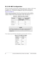
9.7.
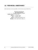
Configuring the Analog Output
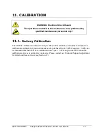
The analog output can be configured for either 0-5V DC or 4-20mA operation. To
change or verify the configuration of the analog output:
1.
Disconnect power from the 465H.
2.
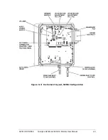
Remove the six screws and the top cover (Rack Mount Configuration) or open
front panel (NEMA Configuration.)
3.
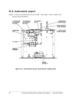
Locate the Mainboard PCA (see Figure 9-1 or Figure 9-2).
4.
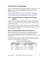
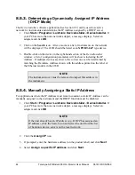
Set the desired operation as shown in Figure 9-4.
5.
Re-Install the top cover or re-secure the front panel (NEMA Configuration.)
REF_DET
TP12
I2
TP9
I1
TP10
ISO_V
TP6
ISO_GND
TP5
DAC
TP4
PRESS
TP8
MEAS
TP18
5.0VREF
TP7
4.096VREF
TP11
+12VL
TP19
REF
TP14
+15V
TP17
-9V
TP16
+12V
TP20
+9V
TP22
3.3V
TP2
DGND
TP3
VCC
TP1
R26
R44
R59
R58
R33
R36
R35
R40
R39
R17
R20
R16
R1
2
R15
R30
R23
R24
R7
R8
R9
R45
R49
R41
R5
C7
C14
J17
J8
J16
R50
R34
R28
J20
J7
U14
X1
C37
+
C49
+
C29
+
C27
+
SDA
TP13
SCL
TP15
MEAS_DET
TP21
R13 R14
R18
SRAM128KX8-SOP
U13
HCF4052B
U22
74HC373
U6
PS1
LAMP INVERTER
R19
J24
C51
J2
VR4
VR6
PCF8575
U9
7407
U12
74HC373
U7
74HC373
U11
R62
R61
R29
SW1
K4
K5
K7
K8
K9
K10
C62
CPU ALIVE
D14
R22
R25
R27
Q2
R54
PR3
PR4
C65
C70
J11
PR2
PR1
R2
SW2
SW4
J5
U29
R60
R63
DCP010515
U21
VR7
LM7805
VR2
C56
C46
C58
Y1
R1
R48
R42
R47
R51
R37
R38
R55
R53
R52
R57
R56
R32
D7
D10
D12
D13
D1
D4
D8
D2
D3
R21
J3
D5
D11
D9
D6
PIC18F8720
U1
7407
U28
M41T0
U18
J6
+15V
J15
J1
C4
PS2
J13
J23
R43
+15V
J14
J10
C50
J19
K6
J4
JP1
J12
Q3
JP5
K1
J21
J18
R31
JP2
JP4
J9
K3
K2
G2
G1
J22
R10
R6
R3
R4
R46
R11
C71
C72
C64
C60
C54
C48
C53
C63
C66
C68
C67
C38
C45
C44
C42
Q1
JP3
C8
C15
C24
C11 C12
C22
C19
C26
C23
C32
SWITCH DIP 10
SW3
C30
C28
C39
C34
C31
C47
C41
+
C40
C36
C61
C35
C59
C57
C25
C43
C33
C69
C17
C18
C6
C52
C3
+
C10
C20
C16
C13
C9
C21
C1
C2
C5
C55
VR5
VR3
TC1044
U27
XTR110
U10
U5
ISO124
U8
U15
U20
U16
U24
U19
U26
U23
U25
LT1181
U4
U2
XPORT XE
U3
VR1
U17
HEATER
D15
R64
R65
R66
R67
AUX
.
.
.
VA
LV
E
Analog Out
RS-485/
Expansion
Expansion
MODULE
Close Indicated Positions Only
RS232
RS485
ETHERNET
ZERO
SPAN
FLOW
+
LINE
EARTH
AC
HIGH VOLTAGE
DANGER!
NEUT
+15V
DI
SP
LA
Y
RE
LA
Y 1
N.C.
COM
N.O.
RE
LA
Y 2
N.C.
COM
N.O.
N.O.
COM
N.C.
RE
LA
Y 3
PCA 05072
REV:
(C)2004
PUMP
+12V
TELEDYNE API
2
4
5
6
7
8
9
10
11
13
14
16
1
3
12
15
VALVE
Analog In
R27
JP4
Q1
JP3
JP4
JP3
R27
Q1
0-5V OUTPUT
4-20mA OUTPUT
Figure 9-4: Mainboard – Analog Output Configuration
Summary of Contents for 465H
Page 2: ......


