2 Installation
MIX 56 User Manual
2-10
Telect, Inc. 122188-10 A0
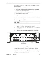
To Cable a System as a Multiplexer
Step
Action
1.
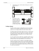
Connect the DS1 signals to the wire-wrap
pins on the front of the chassis:
a. Connect 24 AWG cross-connect wire to
the pins.
b. Route the wire down through the fanning
strip and out.
c. Record designations on the label inside the wire-wrap door.
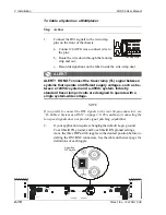
ALERT
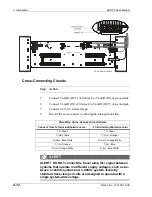
ALERT! DO NOT connect the tracer lamp (TL) signal between
systems that operate on different supply voltages, such as be-
tween a +24Vdc system and a -48Vdc system. Industry
standard tracer lamp circuits are designed to operate with a
single system-wide voltage.
NOTE
If you prefer to connect the DS1 signals to the rear 64-pin connectors, see
“To Cable a System as a DSX” on page 2-9. This method of connecting the
low speed signals does not provide signal patching capabilities.
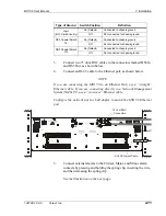
2.
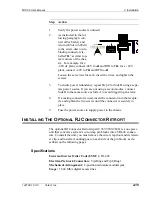
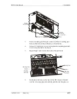
If your application requires changing the default Logic ground,
Coax Shield TX ground, and Coax Shield RX ground settings,
move the three DIP switch toggles to the desired position before in-
stalling the DS3 BNC connectors. See the table on the next page for
definitions of each toggle.
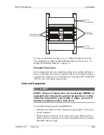
Fanning Strip
+B
–B
+A
–A
+B
–B
+A
–A
3-position
DIP Switch
1
2
3
O
n
Summary of Contents for MIX 56
Page 1: ... MIX 56 122188 10 A0 USER MANUAL ...
Page 6: ...vi Telect Inc 122188 10 A0 ...
Page 10: ...x Telect Inc 122188 10 A0 ...
Page 100: ...4 Software Operation MIX 56 User Manual 4 54 Telect Inc 122188 10 A0 ...
Page 116: ...5 Owner Maintenance MIX 56 User Manual 5 16 Telect Inc 122188 10 A0 ...
Page 123: ......

