www.tekvox.com
1201-MV
79033-MV User Manual
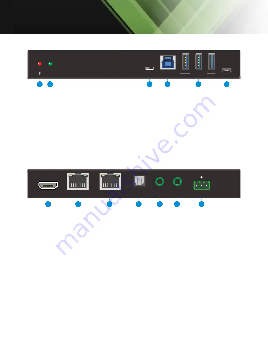
3.3 Receiver Front Panel
1.
POWER LED:
Lights up red when device is powered on
2.
HDMI LED:
Lights up green when there is an HDMI signal output
3.
PC SWITCH:
Select whether the Host PC is connected to the switcher or receiver
4.
PC:
Type-B USB port for Host PC connection. The Host PC can be controlled by the USB
devices (e.g. mouse, keyboard, etc.) which are connected to the USB Type-A ports (DEVICEs).
5.
DEVICES (1~3):
Three type-A USB ports for USB device connection (e.g. mouse, keyboard,
etc.). These USB devices are used to control the selected Host PC.
6.
FW:
Micro-USB for firmware upgrade.
3.4 Receiver Rear Panel
1.
HDMI OUT:
Connects to display device.
2.
HDBT IN:
Connects to the HDBT output port of switcher via CAT cable. The orange LED lights
up when there is a valid HDBaseT link between the switcher and the receiver. The green LED
lights up when the video contains HDCP content.
3.
ETHERNET:
RJ45 port for network signal extension. When the TCP/IP port of the switcher is
connected to network, the port will gain network signal via HDBT input.
4.
SPDIF OUT:
Connects to speaker or amplifier for audio de-embedding.
5.
IR IN:
Connects to IR receiver for IR pass-through.
6.
IR OUT:
Connects to IR emitter for IR pass-through.
7.
RS232:
Connects to a control device (e.g. PC) or a third-party device for RS232 pass-through
control.
HDMI
FW
PC
DEVICES
3
2
1
PC
TX/RX
1
2
3
4
5
6
HDBT IN
HDMI OUT
RS232
Tx
Rx
SPDIF
OUT
IR OUT
IR IN
ETHERNET
1
2
3
4
5
6
7


