


Performance C heck/Calibration— Type 1L40
c. Tune the RF CENTER FREQ to the low end of the fre
quency band (1.5 GHz for units with the Coaxial Mixer, or
12.4 GHz, 18.0 GHz and 26.5 GHz respectively for units with
the W aveguide M ixer assembly).
d. Set the signal generator to a frequency that is 50 MHz
above this low limit (e.g. 1.550 GHz for units with the Coax
ial Mixer). Adjust the generator output until a signal is
visible on the display.
e. Adjust the MIXER PEAKING control for maximum signal
amplitude, then adjust the G A IN and generator output for
a signal amplitude of 4 cm. (Repeat this adjustment each
time the generator frequency is changed.)
f. CHECK— The response flatness across the displayed
spectrum by tuning the RF CENTER FREQ, 25 MHz either side
of the applied signal generator frequency. Signal amplitude
should not change more than ± 1 .5 dB from the average
amplitude or a total of 3dB for units with the Coaxial Mixer.
Amplitude must not change more than ± 3 d B for units with
the Waveguide Mixer assembly.
NOTE
There is a p o ssib ility th a t the reference 5 cm sig
nal a m p litu d e adjustm ent w as set a t the maximum
or minimum response p o in t o f the dispersion w in
d o w . Use the average signal a m p litu d e over the
dispersion w in d o w as the reference.
g. Increase the applied frequency in approximately 2.5
GHz steps for the Coaxial M ixer and in approximately 5
GHz steps for W aveguide Mixers for checking the flatness
over the frequency band. The MIXER PEAKING must be set
for best response at each step.
If the response flatness is not within tolerance, perform the
remaining steps.
When making only a Performance Check, omit the remain
der of this step and proceed to step 14.
The Type 1L40 response flatness and sensitivity is de
pendent on the combined response of the wide band
amplifier, the band pass filter, the low pass filters and the
RF mixer. Each circuit must be adjusted as part of the com
plete system, since the circuit response is dependent on the
impedance presented by the circuits preceding and fo llo w
ing the circuit that is being adjusted.
The low-pass and bandpass filters should require recali
bration only after circuit components have been replaced.
Component replacement and recalibration requires special
equipment and techniques, therefore the analyzer should be
returned to a Tektronix Field Repair Center for repair and
calibration. Contact your local Field O ffice or representa
tive.
This procedure does not require a sweep generator to
check flatness; however, if a sweep generator such as the
Kay model 121C is available it may be used.
h. Equipment setup is shown in Fig. 5-22.
i. Disconnect the Sealectro connector from J120 on the
honeycomb assembly and apply an amplitude calibrated
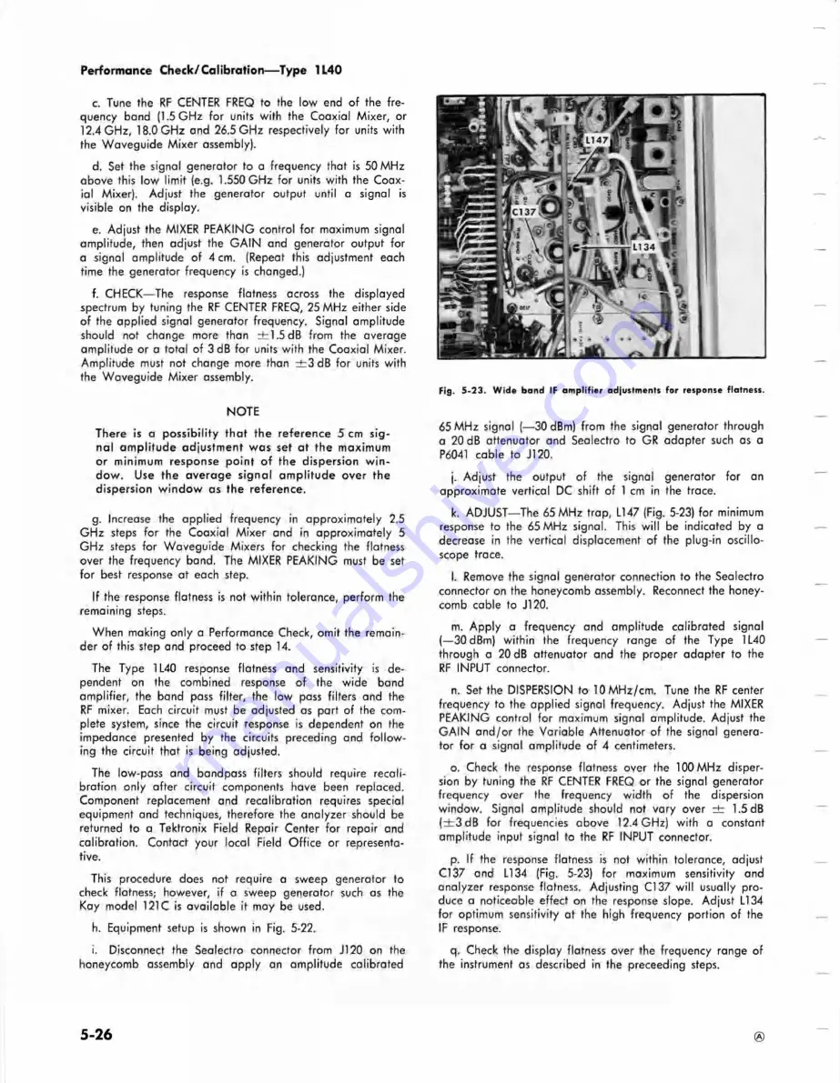
Fig. 5 -2 3 . W ide band IF a m p lifie r adjustments fo r response flatness.
65 MHz signal (— 30 dBm) from the signal generator through
a 20 dB attenuator and Sealectro to GR adapter such as a
P6041 cable to J120.
j. Adjust the output of the signal generator for an
approximate vertical DC shift of 1 cm in the trace.
k. ADJUST— The 65 MHz trap, L147 (Fig. 5-23) for minimum
response to the 65 MHz signal. This w ill be indicated by a
decrease in the vertical displacement of the plug-in oscillo
scope trace.
l
. Remove the signal generator connection to the Sealectro
connector on the honeycomb assembly. Reconnect the honey
comb cable to J120.
m. A pply a frequency and amplitude calibrated signal
(—30 dBm) within the frequency range of the Type 1L40
through a 20 dB attenuator and the proper adapter to the
RF INPUT connector.
n. Set the DISPERSION to lO M H z/cm . Tune the RF center
frequency to the applied signal frequency. Adjust the MIXER
PEAKING control for maximum signal amplitude. Adjust the
GAIN a n d /o r the Variable Attenuator of the signal genera
tor for a signal amplitude of 4 centimeters.
o. Check the response flatness over the 100 MHz disper
sion by tuning the RF CENTER FREQ or the signal generator
frequency over the frequency width of the dispersion
window. Signal amplitude should not vary over ± 1.5 dB
( ± 3 d B for frequencies above 12.4 GHz) with a constant
amplitude input signal to the RF INPUT connector.
p. If the response flatness is not within tolerance, adjust
Cl 37 and LI 34 (Fig. 5-23) for maximum sensitivity and
analyzer response flatness. Adjusting Cl 37 w ill usually pro
duce a noticeable effect on the response slope. Adjust L I34
for optimum sensitivity at the high frequency portion of the
IF response.
q. Check the display flatness over the frequency range of
the instrument as described in the preceeding steps.
5-26
®
Summary of Contents for 1L40
Page 30: ...Fig 3 1 Type 1L40 Block Diagram CO K ISO 2 5 0 MHz 75 MHz Circuit Description Type 1L40 ...
Page 40: ...NOTES ...
Page 54: ...NOTES ...
Page 85: ...NOTES ...
Page 103: ......
Page 117: ...I ...
Page 119: ...T Y P E I L 4 0 S F t C T R U M A N A U V t R A ...
Page 120: ...L R O G 8 R F P H A S E L O C K D I A G R A M A ...
Page 124: ... 75V T Y P L I L A Q S P f c C T R U M A N A L Y Z t R ...
Page 126: ... T y p t S P E C T R u M A N A U V 2 f e R A ...
Page 127: ...4 A P H A S t L O C K C I R C U I T ...
Page 128: ...iv r AMPUH19 1 rRon J9A 4 T Y P E L 4 0 S P E C T R U M A N A L Y Z C R A I ...
Page 130: ......
Page 134: ... IS MHZ IP lO M Hx OSCILLATOR r T Y P E IL 4 0 SPECTRUM ANALYZED ...
Page 135: ... lL I z 5 a or lJ ui Ul X i u tt O a i d id u it l h 5 12 2 a or PO S 3 J3 ...
Page 139: ...DETECTORS i 4 1066 OUTPUT AMPLIPIER ...
Page 140: ...FIG 1 FRONT REAR TYPE 1L40 SPECTRUM ANALYZER ...
Page 141: ...FIG 2 IF CHASSIS PHASE LOCK AS 6 1 ...
Page 142: ...F CHASSIS PHASE LOCK ASSEMBLIES TYPE 1L40 SPECTRUM ANALYZER ...
Page 145: ......


