


Chapter 5 Relay Ladder Logic Programming
104
-
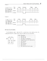
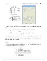
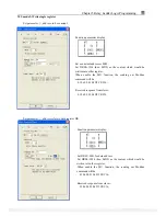
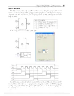
Example:
The state of M01, M02 and M03 are OFF-ON-OFF, so that PWM output pulse is at stage3 like this as setting
above.
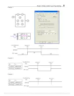
The state of M01, M02 and M03 decide the duty cycle and frequency of PWM output. PWM stages can be
changed by the status of M01, M02 and M03 when P01 is running.
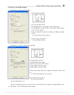
⑥
displays the number of pulse when P01 is
running, but
⑥
equals 0 when P01 is disabled.
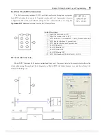
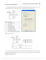
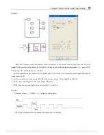
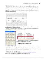
PLSY mode
Only P01 can work under this mode, and the output is Q01. PLSY has 6
parameters
for proper configuration.
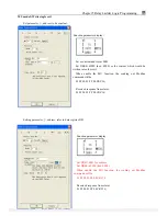
The table below describes the information of PLSY parameters.
Symbol Description
①
PLSY mode (2)
②
Total number of pulse (storing in DRC9)
③
Preset frequency of PLSY (1~1000Hz)
④
Preset pulse number of PLSY(0~32767)
⑤
Output port (Q01)
⑥
PWM code (P01)
PDF compression, OCR, web optimization using a watermarked evaluation copy of CVISION PDFCompressor