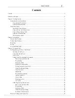
4KA72X023
II
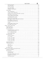
LCD Display and Keypad ..................................................................................................................................... 46
Keypad .......................................................................................................................................................... 46
Original Screen ............................................................................................................................................. 47
LCD Display Main Menu.............................................................................................................................. 50
RTC Daylight saving setting
....................................................................................................................... 55
SG2 system error
......................................................................................................................................... 59
Chapter 4: Parameter passing........................................................................................................................................ 60
SG2 inner data type............................................................................................................................................... 61
Passing parameter out of range ............................................................................................................................. 63
Chapter 5: Relay Ladder Logic Programming .............................................................................................................. 65
Common Memory Types....................................................................................................................................... 66
Specialty Memory Types....................................................................................................................................... 69
Output Instructions................................................................................................................................................ 70
Analog memory type............................................................................................................................................. 71
Timer Instruction................................................................................................................................................... 72
Counter Instructions.............................................................................................................................................. 80
Real Time Clock (RTC) Instructions .................................................................................................................... 90
Comparator Instructions........................................................................................................................................ 98
HMI Display Instructions.................................................................................................................................... 100
PWM Output Instruction (DC Transistor Output Models Only)......................................................................... 103
IO Link/Remote I/O Instruction (SG2-20Vxxx model only) .............................................................................. 106
MU (Modbus) (SG2-20Vxxx model only) ......................................................................................................... 109
SHIFT (shift output)............................................................................................................................................ 116
AQ (Analog Output) ........................................................................................................................................... 117
AS (Add-Subtract) .............................................................................................................................................. 119
MD (MUL-DIV) ................................................................................................................................................. 120
PID (Proportion- Integral- Differential).............................................................................................................. 121
MX (Multiplexer)................................................................................................................................................ 125
AR (Analog-Ramp)............................................................................................................................................. 126
DR (Data register)............................................................................................................................................... 130
Chapter 6: Function Block Diagram Programming .................................................................................................... 132
FBD Instructions ................................................................................................................................................. 133
FBD system memory space................................................................................................................................. 134
Analog................................................................................................................................................................. 136
Analog Input ............................................................................................................................................... 136
Analog Output............................................................................................................................................. 137
Coil Block Instruction......................................................................................................................................... 138
HMI............................................................................................................................................................. 139
PWM function block (only transistor output version)................................................................................. 140
IO Link function block................................................................................................................................ 142
SHIFT function block ................................................................................................................................. 144
Logic Block Instructions ..................................................................................................................................... 145
AND Logic Diagram................................................................................................................................... 145
AND (EDGE) Logic Diagram .................................................................................................................... 145
NAND Logic Diagram................................................................................................................................ 146
NAND (EDGE) Logic Diagram.................................................................................................................. 146
OR Logic Diagram...................................................................................................................................... 146
NOR Logic Diagram ................................................................................................................................... 147
PDF compression, OCR, web optimization using a watermarked evaluation copy of CVISION PDFCompressor


