background image


1-1 

Chapter 1    Safety Precautions 


1.1


Operation Precautions


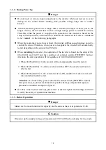
1.1.1.  Before Power Up 


Caution


The line voltage applied must comply with the inverter’s specified input voltage.(See 
product nameplate) 


Danger


Make sure the main circuit connections are correct. L1, L2 and L3 are power-input 
terminals and must not be mistaken for T1, T2 and T3. Otherwise, inverter damage can 
result. 


 Caution 


To avoid the front cover from disengaging or other damage, do not carry the inverter by 
its cover. Support the drive by its heat sink when transporting. Improper handling can 
damage the inverter or injure personnel, and should be avoided. 


To avoid the risk of fire, do not install the inverter on flammable objects. Install on 
nonflammable objects such as metal surfaces. 


If several inverters are placed in the same control panel, provide heat extraction means 
to keep the temperature below 40

 to avoid overheat or fire hazard. 

  When removing or installing the operator keypad, turn OFF the power first, and secure 

the keypad correctly to avoid keypad operation or display failure.


Warning 


This product is sold subject to IEC 61800-3. In a domestic environment this product 
may cause radio interference in which case the user may be required to apply corrective 
measures. 


Motor over temperature protection is not provided. 


Summary of Contents for E310 Series

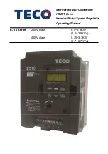
Page 1: ...Microprocessor Controlled I G B T Drive Inverter Motor Speed Regulator Operating Manual E310 Series 200V class 400V class 0 4 1 5KW 1 2 2 9KVA 0 75 3 7KW 1 7 6 7KVA...

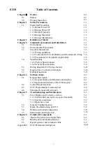
Page 2: ...eries Inverter 3 11 3 6 Description of connection terminals 3 12 3 7 Outline Dimension 3 13 Chapter 4 Software Index 4 1 4 1 Keypad Description 4 1 4 1 1 Keypad Display and Operation Instruction 4 1 4...

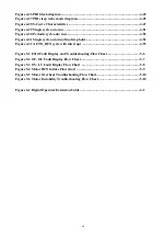
Page 3: ...Board Drive Operation Modes 4 19 Figure 4 6 3 Wires Start Stop Wiring 4 19 Figure 4 7 Drive Start Stop Operation sequences 4 20 Figure 4 8 Acceleration and deceleration Prohibit 4 22 Figure 4 9 UP DO...

Page 4: ...n final step hold 4 52 Figure 4 32 AUTO_RUN cycle with interrupt 4 53 Figure 5 1 E310 Fault Display and Troubleshooting Flow Chart 5 6 Figure 5 2 OC OL Fault Display Flow Chart 5 7 Figure 5 3 OV LV Fa...

Page 5: ...ght will fade z Do not make any connections when the inverter is powered on Do not check parts and signals on circuit boards during the inverter operation z Do not disassemble the inverter or modify a...

Page 6: ...ng can damage the inverter or injure personnel and should be avoided To avoid the risk of fire do not install the inverter on flammable objects Install on nonflammable objects such as metal surfaces I...

Page 7: ...he operation of the inverter is based on the setup of 00 03 or00 04 and 04 09 and the condition of external switch FWD REV button Attention the start operation will be regardless of 04 03 04 04 04 06...

Page 8: ...erter can drive the motor from low speed to high speed Verify the allowable speed range of the motor and the load before operation z Note the settings related to the braking unit z Do not check signal...

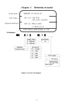
Page 9: ...E31 0 2 01 H Supply voltage Specification 2 200Vclass H 4 400Vclass Adhibition Horsepower 0 standard Type P5 0 5 HP 01 1 HP 02 2 HP 03 3 HP Power supply 05 5 HP 3 Three phase Blank common model for s...

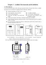
Page 10: ...or moisture Avoid direct sunlight Avoid oil mist and salinity Avoid corrosive liquid and gas Avoid dust lint fibers and small metal filings Keep away from radioactive and flammable materials Avoid el...

Page 11: ...3 2 3 2 Environmental precautions Do not use the inverter in an environment with the following conditions...

Page 12: ...ne end only C Nominal electrical specifications of the terminal Block TM1 Note Nominal values of input and output signals TM2 TM3 follow the specifications of class 2 wiring D Fuse types Drive input f...

Page 13: ...rcuit terminals TM1 Wire gauge 2 0 mm2 terminal screw M3 5 Signal terminals TM2 TM3 Wire gauge 0 80mm2 18 AWG terminal screw M3 model E310 XXX 401 402 403 405 Molded case circuit breaker made by Teco...

Page 14: ...e magnetic contactor as the run stop switch of the inverter AC reactor for power quality improvement When inverters below 200V 400V class 15KW are supplied with high capacity above 600KVA power source...

Page 15: ...noise filter Add a noise filter or separation transformer when sharing the power line with other machines The inverter shares the power line with other machines A noise filter in the output of the ma...

Page 16: ...eed 50 meters C Inverter Ground terminal must be connected to installation ground correctly and according to the required local wiring regulations For 200V class ground resistance should be 100 or les...

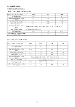
Page 17: ...Output Voltage Three Phase 200 240V Net Weight KG 1 37 1 37 1 47 Allowable momentary power loss time second 1 0 1 0 2 0 Three phase 380 480V model Model E310 XXX 401 402 403 405 Horsepower HP 1 2 3 5...

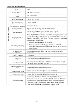
Page 18: ...or automatic procedure control with multifunctional contacts on the terminal block TM2 Frequency Limit Function Upper lower frequency limits and three programmable skip frequencies Carrier frequency 1...

Page 19: ...otect the motor the curve can be set and the inverter 150 1min Over Voltage 200V class DC Voltage 410V 400Vclass DC Voltage 820V Under Voltage 200V class DC Voltage 190V 400Vclass DC Voltage 380V Mome...

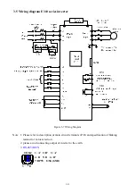
Page 20: ...g Diagram Note 1 Please refer to description of main circuit terminals P R and specification of braking resistor for value selection 2 please avoid connecting output of inverter to the earth 3 RS 485...

Page 21: ...ameters 01 09 01 10 RB Normal close contact RC Common contact 10V Frequency knob VR power source terminal pin 3 AVI Analog frequency signal input terminal AVI 0 10VDC 2 10VDC ACI PID signal input term...

Page 22: ...3 13 3 7 Outline Dimensions unit mm 1 Frame1 single Three phase E310 2P5 201 202 Three phase E310 401 402 Figure 3 8 Frame size 1 Dimensions E310 2P5 201 202 401 402...

Page 23: ...3 14 2 Frame2 Three phase E310 403 405 Figure 3 9 Frame size 2 Dimensions MODEL E310 403 405...

Page 24: ...segment display Refer to operation description of the keypad 2 FWD LED Forward Direction LED action Flash while stopped solid Lit during operation 3 REV LED Reverse Direction LED action Flash while s...

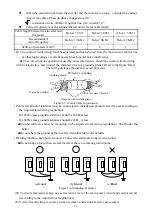
Page 25: ...LED keypad 2seconds later or after Enter operation signal Press DSP to modify the display Power On LED fully Lit LED flashing HZ RPM HZ RPM HZ RPM FUN FUN FUN FUN VOLT VOLT AMP Figure 4 2 LED Keypad...

Page 26: ...al inverter current 2 Input correct VF Pattern parameter 05 04 05 09 3 When the nameplate of the motor is unknown the inverter will be set by default to parameters according to the standard TECO motor...

Page 27: ...er parameter group 13 Auto Run Auto Sequencer function group 0 The basic parameters group Function Code No Description Range Code Factory Setting Remarks 00 00 Control Mode 0 Volts Hz 1 Vector 0 00 01...

Page 28: ...0 5 1 1 External terminal digital signal input function group Function Code No Description Range Code Factory Setting Remarks 01 00 Multifunction Input Term S1 0 Forward Stop Command 1 Reverse Stop C...

Page 29: ...uency Threshold Level 1 11 Frequency Reached 5 Frequency Threshold Level 1 11 Frequency Reached 6 Auto Restart 7 Momentary AC Power Loss 8 Emergency Stop Mode 9 Base Block Stop Mode 10 Motor Overload...

Page 30: ...e 0 1 02 06 ACI function Select 0 PID feedback signal 1 ACI Bias signal input 0 02 07 ACI Signal Verification Scan 1 100 x 4ms 50 02 08 ACI Gain 0 1000 100 1 02 09 ACI Bias 0 0 100 0 0 0 1 02 10 ACI B...

Page 31: ...0 1 3600 0 10 0 1 03 20 Preset Speed1 Dectime s 0 1 3600 0 10 0 1 03 21 Preset Speed2 Acctime s 0 1 3600 0 10 0 1 03 22 Preset Speed2 Dectime s 0 1 3600 0 10 0 1 03 23 Preset Speed3 Acctime s 0 1 360...

Page 32: ...Run Command is Off 1 Enable Reset when Run Command is On or Off 0 04 09 Direct Running After Power Up 0 Enable Direct running after power up 1 Disable Direct running after power up 1 04 10 Delay ON T...

Page 33: ...08 Medium Frequency1 Hz 0 10 400 00 10 00 12 00 5 05 09 Medium Frequency Voltage Ratio1 0 0 100 0 20 0 5 05 10 Minimum Frequency Hz 0 10 400 00 0 50 0 60 5 05 11 Minimum Frequency VoltageRatio 0 0 10...

Page 34: ...er Rated Current 200 07 04 over voltage Prevention Level in Run Mode 350 0 VDC 390 0 VDC 700 0 VDC 780 0 VDC 380 0 760 0 07 05 Electronic Motor Overload Protection Operation Mode 0 Enable Electronic M...

Page 35: ...tion Code No Description Range Code Factory Setting Remarks 08 00 Assigned Communication Station Number 1 32 1 2 4 08 01 RTU code ASCII code select 0 RTU code 1 ASCII code 0 2 3 08 02 Baud Rate Settin...

Page 36: ...ive STOPS After Feedback Loss 0 09 09 Feedback Loss Detection Level 0 100 0 09 10 Feedback Loss Detection Delay Time S 0 0 25 0 1 0 09 11 Integration Limit Value 0 109 100 1 09 12 09 13 Reserved Reser...

Page 37: ...abled 0 10 17 Count Down Completion 0 9999 0 11 Keypad display group Function Code No Description Range Code Factory Setting Remarks 11 00 Display Mode xxxx0 Disable Motor Current Display xxxx1 Enable...

Page 38: ...35 00000 13 Auto Run function group Function Code No Description Range Code Factory Setting Remarks 13 00 Auto Run sequencer mode selection 0 Disabled 1 Single cycle Continues to run from the unfinish...

Page 39: ...Time Setting 6 13 23 Auto_ Run Mode Running Time Setting 7 13 23 13 31 Reserved Reserved 13 32 Auto_ Run Mode Running Direction 0 0 stop 1 forward 2 reverse 0 13 33 Auto_ Run Mode Running Direction 1...

Page 40: ...03 00 04 1 please refer to parameter 04 03 04 04 04 06 04 07 for detailed description in order to ensure safety of operators and machines 3 00 03 00 04 2 the inverter is controlled by Communication 4...

Page 41: ...0 01 05 is set 07 the second acceleration and deceleration time the first acceleration deceleration or the second acceleration deceleration will be set by OFF or ON the external input terminal 3 When...

Page 42: ...valid 2 When operation command 00 03 00 04 1 external terminal control the stop button for emergency is available Refer to04 02 for detail description 3 That both forward and reverse commands are ON...

Page 43: ...xternal terminals S1 on is Jog forward S2 on is Jog reverse Group1 External terminal digital signal input function group Multifunction input terminals TM2 S1 S6 controlling 01 00 05 0 Forward Stop Com...

Page 44: ...of parameters 3 01 to 3 07 and in relation to the operation of input terminals 1 to 3 as shown in the table below Output frequency preset value Multifunction terminal 3 Preset value 4 Multifunction te...

Page 45: ...l accelerate decelerate until the command is released The inverter runs at the speed setting at the time of release The inverter will ramp stop or Free Fun stop which is determined by the 04 01 as lon...

Page 46: ...termal terminal s6 is set a function of 20 after turning it on then off once the counter value increase 1 In vector mode the extermal terminal S6 function of counter trigger signal input is disabled 1...

Page 47: ...set frequency is held as the inverter stops and the UP Down function is disabled 1 When Up Down is used the preset frequency is reset to 0 Hz as the inverter stops 2 When Up Down is used the preset fr...

Page 48: ...Relay RY1 Operation Mode RC RB RA terminal 01 10 Output Relay TR1 Operation Mode SYN SYN terminal 0 Run 1 Fault 2 Frequency Reached 3 Set Frequency 01 11 01 12 4 Frequency Threshold Level 01 11 Freque...

Page 49: ...6 01 09 10 3 Arbitrary frequency consistency Fout 01 11 01 12 01 09 10 4 Frequency detection Fout 01 11 Figure 4 12 Frequency within specified range example Figure 4 13 Frequency outside of range exam...

Page 50: ...type select xxxx0 S6 NO xxxx1 S6 NC Note NO Normal open NC Normal close The switches type is decided by 01 13 01 14 Because of different types of switches select switches type is necessary If set 01 1...

Page 51: ...put ACI To regulate the Offset of the Keypad VR or AVI analog input only the signal of 0 20 mAor4 20mA 02 07 ACI signal verification Scan Time 1 100 4ms 02 08 ACI Gain 0 1000 02 09 ACI Bias 0 0 100 0...

Page 52: ...egative 02 16 FM Slope 0 positive 1 Negative 02 17 Analog Signals Fluctuation of Filter Coefficients 1 100 User can adjust the filter coefficients depend on the analog signals fluctuation on stable si...

Page 53: ...time Dec time is determined by the03 01 03 08 Function Description 1 Formula for calculating acceleration and deceleration time The denominator is base on the rated frequency of motor 06 04 Acctime pa...

Page 54: ...me of each segment like this a 03 17 03 01 06 04 b 03 18 03 01 06 04 c 03 19 03 02 06 04 d 03 20 03 02 06 04 mode2 When the run command is continuous calculate acceleration and deceleration time of ea...

Page 55: ...04 02 0 The STOP key is available for controlling the inverter to stop 04 03 Momentary power loss and restart 0 Momentary Power Loss and Restart disable 1 Momentary power loss and restart enable 2 Mom...

Page 56: ...erter will not auto restart after trips due to fault 2 04 07 0 04 06 0 The inverter will conduct SPIN START in 0 5 second after trips due to fault The motor will Coast to stop while the output is swit...

Page 57: ...n input power is turned off CPU detects the DC bus Voltage and as soon as DC bus Voltage becomes lower than190V 220V system or 380V 440V system then the KEB function is activated 3 When KEB function i...

Page 58: ...Frequency2 Hz 0 10 400 0Hz 05 07 Medium Frequency Voltage Ratio2 0 0 100 0 05 08 Medium Frequency1 Hz 0 10 400 0Hz 05 09 Medium Frequency Voltage Ratio1 0 0 100 0 05 10 Minimum Frequency Hz 0 10 400 0...

Page 59: ...e 1 High start torque 10 11 2 12 3 Decreasing torque 4 Decreasing torque 13 5 14 Constant torque 6 Constant torque 15 7 16 8 17 V 100 B C 1 5 3 0 60 400 Hz V 1 3 2 5 50 400 Hz V 100 B C 1 3 25 50 400...

Page 60: ...invalid 4 When the induction motor is in running there must be slip due to the load It is necessary to boost voltage to improve the precision of the speed Slip frequency boost Output Current 05 01 05...

Page 61: ...e If the motor load is determined to be too large increase the output torque load current compensation gain Torque Speed curve pattern Operating frequency range 0 Motor rate frequency When the motor o...

Page 62: ...rease 06 05 setting value at the same time 06 11 Low frequency voltage compensation Performance During low frequency Increase 06 11 setting value to increase output voltage and low frequency torque De...

Page 63: ...processed materials etc will cause the inverter to trip thus inconvenience users When the operating torque of the inverter exceeds the setting of 07 03 the inverter will lower the output frequency fol...

Page 64: ...detected for a duration of time which is set in parameter 07 12 2 07 10 0 If there is over torque the inverter coasts to stop and flashes OL3 It is necessary to press RESET or external terminal to con...

Page 65: ...he PC or PLC Broadcast mode then all these inverters will be controlled in communication mode regardless of the setting of parameter 08 00 Note a Communication data parameters 08 02 08 03 08 04 8 05 f...

Page 66: ...ing speed reference The PID target value can be set by parameter 00 05 006 for example the frequency command target can be set from Operator keypad AI1 Analogue input or multi function analog input te...

Page 67: ...s 0 0 100 0 09 03 Integrate time for I control 09 04 Differentiation Time s 0 00 10 00 09 04 Differential time for D control 09 05 PID Offset 0 Positive Direction 1 Negative Direction 09 06 PID Offse...

Page 68: ...D setting frequency source Target Value 09 14 set the sleep threshold frequency Unit HZ 09 15 set the time for sleep delay Unit sec 09 16 set the wake threshold frequency Unit HZ 09 17 set the time fo...

Page 69: ...gher than ten times the max running frequency Example If the Max running frequency 400Hz then set the carrier Frequency higher than 4 KHz If the Max running frequency 300Hz then set the carrier freque...

Page 70: ...ased on the rated frequency of motor 06 04 Please refer to the parameter 00 09 00 10 10 11 Skip frequency 1 Hz 0 00 400 00 10 12 Skip frequency 2 Hz 0 00 400 00 10 13 Skip frequency 3 Hz 0 00 400 00 1...

Page 71: ...temperature Display 0xxxx Disable PID feedback Display 1xxxx Enable PID feedback Display 11 01 Custom Units Line Speed Value 0 65535 The max preset line value of 11 01 is equal to the rated frequency...

Page 72: ...reset key is pressed The log content will change to 1 2 3 4 E g the fault log content is 1 OC C this indicates the latest fault is OC C etc 12 03 Accumulated Operation Time 1 Hours 0 23 12 04 Accumula...

Page 73: ...ontinues to run from the unfinished step if restarted 3 Single cycle then holds the speed of final step to run Continues to run from the unfinished step if restarted 4 Single cycle Starts a new cycle...

Page 74: ...parameters 13 01 13 39 3 Auto run mode sequencer operation as selected by parameter 13 00 can be set up as follows a Setting multi step frequency commands by using the available multi step frequency...

Page 75: ...3 01 30Hz 13 02 50Hz 13 07 20Hz 13 16 20s 13 17 25s 13 18 30s 13 23 40s 13 32 1 13 33 1 13 34 1 13 39 1 FWD 13 04 13 06 0Hz 13 20 13 22 0s 13 35 13 38 0 Note 13 00 1 3 If the inverter stops and re sta...

Page 76: ...ency Run Command Continue running from unfinished step stop run run time Output Frequency Run Command begin a new cycle stop run run ACC DEC time follow the setting of 00 09 00 10 or 10 05 10 06 in Au...

Page 77: ...T module damaged 1 Inspect the motor 2 Inspect the wiring 3 Replace the transistor module Over current at deceleration The preset deceleration time is too short Set a longer deceleration time Over cur...

Page 78: ...nverter is set for external terminal control mode 00 03 00 04 1 and direct start is disabled 04 09 1 The inverter cannot be started and will flash STP1 The run input is active at power up refer to des...

Page 79: ...parameter in STOP mode Parameter setting error 1 00 08 is within the range of 10 11 10 14 or 10 12 10 14 or 10 13 10 14 2 00 07 00 08 3 Setting error while Performing Auto tuning e g 00 03 00 04 0 00...

Page 80: ...T1 T2 and T3 correct Wiring must match U V and W terminals of the motor Motor runs in wrong direction Are wiring for forward and reverse signals correct Check for correct wiring Is the wiring for the...

Page 81: ...fault values in 12 2 YES YES YES YES YES YES YES YES Is the main circuit DM intact Is the main circuit I G B T intact Is the DC input voltage controlling the power correct Replace control board and d...

Page 82: ...rd Replace the control board Replace the control board The inverter is failed Perform detailed check NO NO NO NO YES YES YES YES Is the frequency value displayed in operation unit Are there voltage ou...

Page 83: ...board Perform detailed check The inverter is faulted NO NO YES YES YES YES YES YES NO NO NO NO NO NO YES Is the main circuit I G B T working Any visual abnormalities Is FWD LED illuminated Is the outp...

Page 84: ...board Perform detailed check The inverter is failed NO YES YES NO NO YES Is the main circuit fuse intact Any visual abnormalities Is FWD LED still illuminated after flash Connect the motor to run The...

Page 85: ...The power is abnormal Incorrect wiring E310fault The operation switch is set to RUN position E310fault E310fault YES within 3 of the normal value YES voltage deviation between output pairs are even i...

Page 86: ...unevenly Is the load fluctuating Does it happen during deceleration Are the output voltages between T1 T2 T3 balanced Any mechanical vibration or gear backlash Is the acceleration time correct Increa...

Page 87: ...ure the voltage with a multi tester Voltage must conform with the specifications Improve input voltage Are secure parts loose Is the terminal base damaged External terminals and internal mounting scre...

Page 88: ...pacitors 1 Clean up the accumulation of any dust inside the inverter 2 Check if there are any loose terminal screws and tighten them 3 Insulation tests a Disconnect all leads connecting the INVERTER w...

Page 89: ...10 405 XXX 10 0 2 2 8 8 3 98 6 2 Braking unit and braking resistor Braking resistor Specification Inverter Model Suitable Motor Capacity HP Suitable Motor Capacity KW W Number used Braking resistor Du...

Page 90: ...on B Operation procedure 1 Turn off the power Supply the following procedures should be performed after there is no display on the keypad 2 Remove the keypad 3 Connect the inverter and the keypad with...

Page 91: ...6 3 Extension KEYPAD installation 1 KEYPAD installation Dimensions 5 4 6 7 a 5 3 0 2 Dimension for remote keypad a Keypad hatch Installation Dimension E31DOP 01...

Page 92: ...eypad Installation Dimension for nut superaddition gasket and nut c none gasket and nut Keypad Installation Dimension E31DOP 01 E31DOP 01 fixing board fixing board flap gasket M3 elastomeric gasket M3...

Page 93: ...04 05 01 08 02 00 12 03 05 05 02 08 03 00 13 03 06 05 03 08 04 00 14 03 07 05 04 08 05 01 00 03 08 05 05 08 06 01 01 03 17 05 06 08 07 01 02 03 18 05 07 08 08 01 03 03 19 05 08 08 09 01 04 03 20 05 09...

Page 94: ...ode Setting content 10 06 11 01 13 00 13 21 10 07 11 02 13 01 13 22 10 08 11 07 13 02 13 23 10 09 11 08 13 03 13 32 10 10 12 00 13 04 13 33 10 11 12 01 13 05 13 34 10 12 12 02 13 06 13 35 10 13 12 03...

Page 95: ...ecause of improvement of the product modification or changes in specification this manual is subject to change without notice 10F No 3 1 Yuancyu St Nangang District Taipei City 115 Taiwan Tel 886 2 66...

Reviews: