


3-11
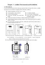
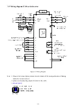
3.5 Wiring diagram E310 series inverter
(
(
(
Figure 3-7 Wiring Diagram
Note 1: Please refer to description of main circuit terminals (P, R) and specification of braking
resistor for value selection.
2: please avoid connecting output of inverter to the earth.
3: RS-485 (RJ45)
CON2
RY1
TR1
1
8
1: A
′
2: B
′
3: A
′
4: R 5: D 6: B
′
7:DP5V 8:SG(GND)