


26
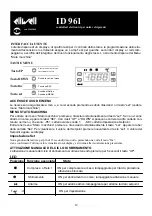
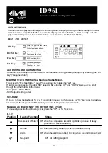
DIAGNOSTIC
The alarm condition is always signalled by
the buzzer (if present) and by the led of
The alarm icon
The alarm signal produced by a faulty
thermostat probe (probe 1) is shown as E1
on the instrument display.
When the sensor detects an error condi-
tion:
• the code E1 is displayed
•
the compressor is activated as indi-
cated by the "On" and "Off" para-
meters if
•
programmed for the duty cycle or:
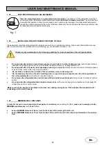
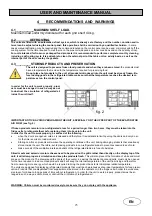
INSTALLATION
The instrument is designed for panel moun-
ting. Make a hole of 29x71 mm, insert the
instrument and fix it using the brackets
provided. Do not mount the instrument in
humid and/or dirty places; it is suitable for
use in ordinary polluted places. Ventilate
the place in proximity to the instrument
colling slits.
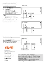
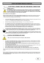
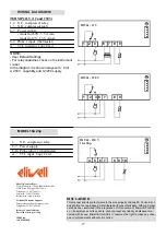
ELECTRICAL WIRING
Attention! Never work on electrical
connections when the machine is
switched on. The instrument is equipped
with screw terminal boards for connection
of electrical cables with a diameter of 2.5
mm2 (one conductor only per terminal for
power connections).For the capacity of
the terminals, see the label on the instru-
ment.The relay contacts are voltage free.
Do not exceed the maximum current allo-
wed; In case of higher loads, use an ap-
propriate contactor. Make sure the power
supplym voltage complies with the one
required by the instrument. In 12V
versions the power supply must be provi-
ded by a security transformer with the
protection of a delayed 250 mA fuse.
Probes have no connection polarity and
can be extended using a regular bipolar
cable (note that the extension of the
probes affects the EMC electromagnetic
compatibility of the instrument: pay
extreme attention to wiring).
Probe cables, power supply cables and
The TTL serial cables should be distant
from power cables.
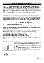
CONDITIONS OF USE
PERMITTED USE
For safety reasons the instrument must
Be installed and used according to the
instruction provided and in particular,
under normal conditions, parts bearing
dangerous voltage levels must not be
accessible.
The device must be adequately protected
from water and dust as per the application
and must also only be accessible via the
use of tools (with the exception of the
frontlet).
The device is ideally suited for use on
household appliances and/or similar
refrigeration equipment and has been t
Ested with regard to the aspects concerni-
ne European reference standards on sa-
fety. It is classified as follows:
• according to its manufacture: as an
automatic electronic control device to be
incorporated by independent mounting;
• according to its automatic operating fea-
tures: as a 1 B-type operated control type;
as a Class A device in relation to the
category and structure of the software
UNPERMITTED USE
Any other use other than that permitted is
de facto prohibited. It should be noted
that the relay contacts provided are of a
practical type and therefore subject to
fault. Any protection devices required by
product standards or dictated by common
sense due to obvious safety reasons
should be applied externally.
LIABILITY ABD RESIDUAL
RISKS
Eliwell & Controlli s.r.l. shall not be liable
for any damages deriving from:
- installation/use other than that prescri-
bed and, in particular, that which does
not comply with safety standards anticipa-
ted by regulations and/or those given
herein;
- use on boards which do not guarantee
adequate protection against electric
shock,
water or dust under the conditions of
assembly applied;
- use on boards which allow access to
dangerous parts without the use of tools;
- tampering with and/or alteration of the
products;
- installation/use on boards that do not
comply with the standards and regula-
tions in force
TECHNICAL DATA
Frontal panel protection: IP65.
Casing: plastic body in resin type
PC+ABS UL94 V-0, inspection window in
polycarbonate, buttons in thermoplastic
resin.
Dimensions: frontal panel 74x32 mm,
depth 60 mm.
Installation: on panel, with drilling tem-
plate 71x29 mm (+0.2/–0.1 mm).
PLEASE NOTE: The technical data
included in this document, related to
measurement (range, accuracy,
resolution, etc.) refer to the instru-
ment itself, and not to its equipment
such as, for example, sensors.This
means, for example, that sensor(s)
error(s) shall be added to the instru-
ment’s one.
Display
Error
Ont Oft Compressor output
0
0 OFF
0
>0 OFF
>0
0 ON
>0
>0
dc
MODEL 16A 2hp
Digital output: 1 N.O. relay SPST
16A 2hp; 250VA.
Consumption: 3 VA max.
Power supply: 230 Va ±10% 50/60 Hz.
*
NOTE 1
: Switch off and switch on again
the instrument after changing
the input type NTC/PTC (par. H00)
NOTE 2
: check the power supply specified
on the instrument label; for relay and
power supply capacities ( contact the
Sales Office).
Use temperature: –5…55 °C.
Storage temperature.: –30…85 °C.
Use environment humidity: 10…90 % RH
(not condensing).
Storage environment humidity: 10…90%
RH
(not condensing).
Viewing range: –50…99 without decimal
point on 2 digit + mark display.
Analog inputs: one PTC or NTC input
(selectable through parameter H00*).
Serial: TTL for connection to Copy Card.
Digital outputs: 1 relay contact
SPDT 8(3)A 250Va.
Measuring range: from –50 to 99 °C.
Accuracy: 0.5% better than end scale + 1
digit.
Resolution: 1°C.
Consumption:
• model 230V: 3 VA max.
• model 12V: 1,5 VA max.
Power supply: 12 Va/c ±10% or 230Va
±10% 50/60 Hz.
Summary of Contents for GN 1/3
Page 15: ...Note ...
Page 29: ...Note ...
Page 43: ...43 ...
Page 49: ...Note ...
Page 50: ...Note ...
Page 51: ...Note ...


