


TFA2-596 - TFA4-1192
58
JP10
BATT
LED LINE
LED RUN
LED USB
JP4
BOOT
JP5
PROG
JP2
RESET
JP1
WDT
JP8
RS485
SW1
1
2
3
4
5
6
7
8
9
10
A (TEL)
11
B (TEL)
12
A (LINE)
13
B (LINE)
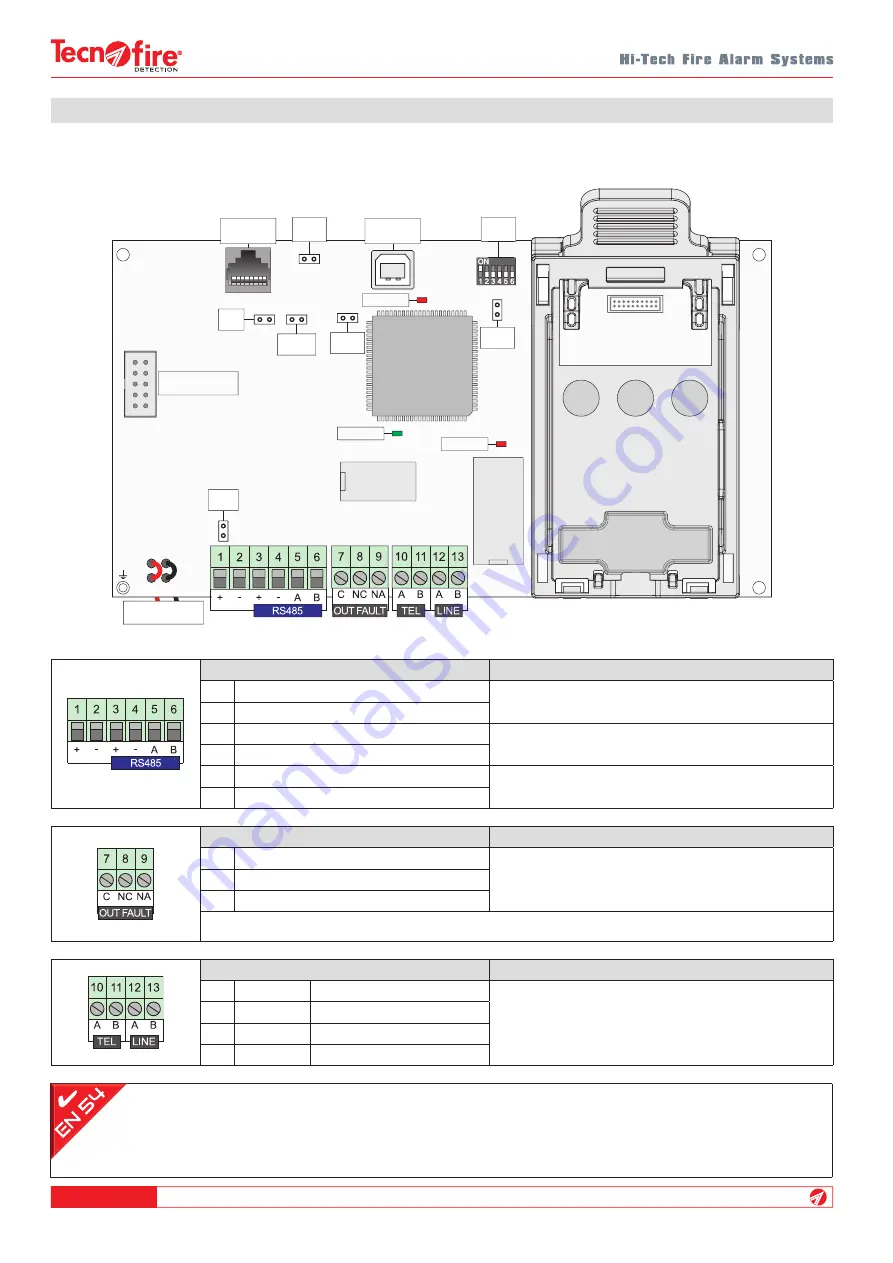
10-7 - Telephone communicator
The electronics of the TFCOM telephone communicator are divided into two parts, the CPU board and the LED board.
RS485 serial bus
Notes
Positive power supply voltage
24V DC power supply input
Negative power supply voltage
Positive power supply voltage
24V DC power supply output
Negative power supply voltage
Channel A serial bus
Serial bus communication channels
Channel B serial bus
Failure output
Notes
Common contact
Failure relay output with free contact
PTC protected (I max. 0.75A)
Normally closed contact
Normally open contact
N.B.
The state indicated for the terminals 8 and 9 is in the condition of unpowered telephone communicator. With the telephone
communicator powered, the state of the terminals is reversed: terminal 8 is in NO state and terminal 9 is in NC state
Warning:
the failure output OUT FAULT (terminals 7, 8, 9) is not supervised (type J according to EN 54-1 nomenclature) and
therefore, in accordance with EN 54-2, should not be used to control transmission devices for failure alarm.
In accordance with EN 54-21, the serial bus power supply consists of two pairs of power supply terminals (terninals 1, 2, 3, 4).
Telephone line
Notes
Telephone line output A
PSTN telephone line (DC)
Telephone line output B
Telephone line input A
Telephone line input B
BATTERY
LED board
connector
USB
Port
TTL
Port
Summary of Contents for Tecnofire TFA2-596
Page 2: ...TFA2 596 TFA4 1192 2...
Page 4: ...TFA2 596 TFA4 1192 4...
Page 10: ...TFA2 596 TFA4 1192 10...
Page 14: ...TFA2 596 TFA4 1192 14...
Page 28: ...TFA2 596 TFA4 1192 28...
Page 32: ...TFA2 596 TFA4 1192 32...
Page 40: ...TFA2 596 TFA4 1192 40...
Page 50: ...TFA2 596 TFA4 1192 50...
Page 62: ...TFA2 596 TFA4 1192 62 NOTES...
Page 63: ......