


©
Technosoft 2007
13
PIM2401 Technical Reference
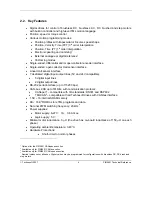
Digital Inputs
All voltages referenced to GND.
Min.
Typ. Max.
Units
Logic “LOW”
-0.5
0
0.8
Logic “HIGH”
2
5÷24
28
Input voltage
Absolute maximum, surge (duration
≤
1S)
†
-25 +30
V
Logic ‘HIGH’; Internal 4.7 K
Ω
pull-up to +5V
0 0 0
Input current
Logic “LOW”
0.8
1
1.3
mA
Input frequency
0
250
KHz
Minimum pulse width
5
µS
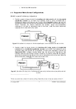
Digital Outputs
All voltages referenced to GND.
Min.
Typ. Max.
Units
Logic “LOW”
-0.5
0
0.2
Logic “HIGH” ; Output current = 0
2.4
4.4
+V
DC
Output voltage
Absolute maximum, duration < 1 ms
-1
+V
DC
+
0.5
V
Logic “HIGH”; Load connected to GND
10
Output current
Logic “LOW”
50
mA
ESD Protection
Human Body Model (100 pF, 1.5 k
Ω
)
±
25
KV
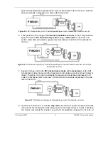
Encoder Inputs
Min.
Typ. Max.
Units
Standards compliance
Differential / TTL / CMOS /
open-collector
Low level input current
Internal 470
Ω
pull-ups to +5 V
DC
10 12 mA
Input threshold voltage
In single-ended mode (TTL / CMOS /
/ open-collector)
1.8 1.9 2 V
Input hysteresis
0.1
0.2
0.5
V
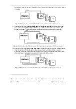
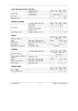
Analog Inputs (Ref, Tacho)
Referenced to GND
Min.
Typ. Max.
Units
Voltage range
0
+5
V
Input impedance
16
K
Ω
Resolution
10
bits
Differential linearity
Guaranteed 10-bit no-missing-codes
0.09
% FS
1
Offset error
±
0.3
% FS
1
Gain error
±
5
% FS
1
Bandwidth (-3 dB)
250 Hz
Summary of Contents for PIM2401
Page 2: ......
Page 4: ......
Page 8: ... Technosoft 2007 VI PIM2401 Technical Reference ...
Page 90: ... Technosoft 2007 80 PIM2401 Technical Reference This page is empty ...
Page 91: ......
Page 92: ......


