©
Technosoft 2007
29
IPS110 Technical Reference
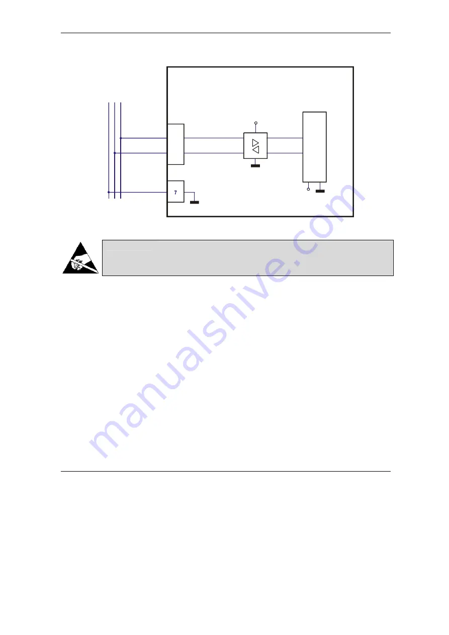
3.2.11. CAN Communication connection
11
J2
GND
+3.3V
CAN_H
CAN_L
12
IPS110
v1.0
CAN connection
CAN transceiver
+5V
To Previous Node
To Next Node
Mo
ti
o
n
C
h
ip
TM
J1
Figure 3.16.
CAN connection
CAUTION!
THE CANBUS CONNECTOR SIGNALS ARE ELECTRO-
STATICALLY SENSITIVE. THE IPS110 SHALL BE
HANDLED ONLY IN AN ESD PROTECTED ENVIRONMENT.
Remarks:
1. The CAN network requires two 120
Ω
termination resistors even for short cables. These
resistors are not included on the drive.
2. Both CAN signals are NOT insulated from all other IPS110 circuits .
3.
CAN signals (CAN_H and CAN_L pins of J2 connector) are
not connected
pins on the
IPS110 drive execution P045.001.E001.
3.2.11.1 Recommendations for CAN Wiring
a) Build CAN network using cables with 2-pairs of twisted wires (2 wires/pair) as follows: one
pair for CAN_H with CAN_L and the other pair for CAN_V+ with CAN_GND. The cable
impedance must be 105 ... 135 ohms (120 ohms typical) and a capacitance below
30pF/meter.
b) When total CAN bus length is over 40 meters, it is mandatory to use shielded twisted cables.
Connect the cable shield to earth/shield.
c) When using a printed circuit board (PCB) motherboard based on FR-4 material, build the
CAN network using a pair of 12mil (0.012”) tracks, spaced 8 to 10mils (0.008”…0.010”) apart,
placed over a local ground plane (microstrip) which extends at least 1mm left and right to the
tracks.
Summary of Contents for IPS110
Page 2: ......
Page 4: ......
Page 6: ......
Page 12: ... Technosoft 2007 VI IPS110 Technical Reference ...
Page 82: ... Technosoft 2007 70 IPS110 Technical Reference This page is empty ...
Page 83: ......
Page 84: ......


