7
5.5 - STARTING
• Initial condition:
- Machine hydraulically and electrically connected ready to operate.
- Operating mode remote changeover switch is in required position (heating or cooling).
- The remote On/Off contact is open (off).
• Turn the installation on.
• The display comes on and shows the water temperature (read by the control probe S1).
• Close the possible remote on/off contact (not supplied) if it is not connected (see paragraph 4.2.3).
• The indicator lamp corresponding to the selected mode lights up:
- indicator lamp (7) : Cooling,
- indicator lamp (8) : Heating.
• The compressor "ON" indicator light (6) comes on if necessary (see diagram paragraph 5.4). If the light flashes, it means that
the compressor is starting required but that a safety delay is in progress. This light stays on when the compressor has started.
• To stop the unit, open the remote On/Off contact (in this case, restart is automatic as soon as this contact is closed).
The operating mode indicator lights (7) and (8) and the compressor operation light (6) go off.
PRG
mute
SEL
µ
chiller
5 sec
CAUTION: Changing the operating mode (heating/cooling) must only be done when the machine is stopped.
• It is possible to stop and restart the current mode (selected remotely) by pressing the
▲
key
(2) for the cooling mode or the
▼
key (3) for the heating mode.
NOTE:
The controller’s anti-short cycle system requires that the compressor operate for a minimum
amount of time. If the machine should stop, the compressor may continue to function for a certain
amount of time (150 seconds max.).
PRG
mute
SEL
µ
chiller
5 sec
comp
x 100
PRG
mute
SEL
µchiller
the PRG (1) key. If during the adjustment procedure no key is pressed for 60 seconds (this period is indicated by the display
flashing), the system automatically reverts to normal operation and display without storing the latest parameter changes.
5.6 - ADJUSTING AND DISPLAYING THE PARAMETERS
• Parameters accessible by pressing the SEL (4) key for 5 seconds.
• The display displays the code of the 1st parameter on the list ("r1" - see below).
• By pressing the
▲
(2) or
▼
(3) keys, scroll through the parameter codes until you reach the one
you want.
• Press SEL (4) to find out the value of the corresponding parameter.
• The value of the parameter can if necessary be changed using the
▲
(2) and
▼
(3) keys.
• Press SEL (4) to re-display the parameter codes.
• To store the parameters which have been changed and to exit the adjustment procedure, press
Code
Parameters
Factory
setting
Installation
setting
Adjustment
range
22
°
C
2 k
35
°
C
2 k
-
-
-
-
-
-
-
-
Probe located on water return
Set point
Cooling ("Summer")
Differential
Cooling
Set point
Heating ("Winter")
Differential
Heating
Water heat exchanger temperature
(Probe S2 for anti-freeze)
Air heat exchanger temperature
(Probe S3)
Compressor hour meter
Pump hour meter
r 1
r 2
r 3
r 4
r 6
r 8
c 9
c C
Display only
10 to 30
°
C
0.3 to 19.9 k
25 to 45
°
C
0.3 to 19.9 k
-
-
-
-
Remarks
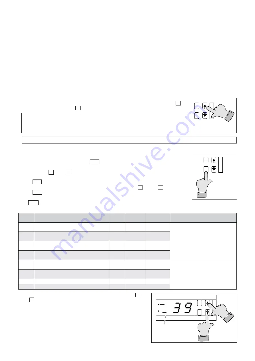
• The hour meters are zeroed by pressing simultaneously on the
▲
(2)
and
▼
(3) keys.
• Note:
The configuration and parameterization of each machine are factory-
set for optimal "Cooling/Heating Floor" operation.
If light (9) is on,
multiply the time
displayed by 100.


