background image

17. Touch the up and down arrows to set the desired number of strokes per

dispensing cycle.

18. Touch the ‘Accept’ icon to save and exit

19. Enter all desired dispensing parameters, then touch the ‘Save’ icon.

Note:

 The system will automatically calculate and display the operating

frequency  

  based on the entered dispensing parameters.

9.5.6


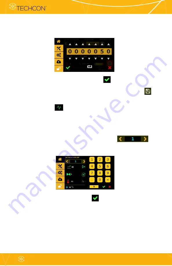
  Calling Up Dispensing Parameters 

    The controller has 50 memory cells store all dispensing parameters. 

1.

Touch the forward or backward arrow to select
the desired memory cell or touch the value to type in a specific
location.

2.

Touch the ‘Accept’ icon to exit.

techcon.com/contact-us


48


Jet Valve Dispensing System User Guide

TS9800 

& TS980

Summary of Contents for TS980

Page 1: ...The fastest non contact Jet Valve dispensing system techcon com contact us 1 Jet Valve Dispensing System User Guide TS9800 TS980 ...

Page 2: ...ng Connection 6 5 Setup 7 VALVE REMOVAL AND CLEANING 7 1 Valve Removal 7 2 Installation of New Nozzle Insert 2 7 3 Cleaning 8 TS9800 PIEZO JET VALVE 8 1 Valve Modules 8 2 Technical Specifications 8 3 Special Features 8 4 Materials Applied 9 TS980 JET VALVE CONTROLLER 9 1 Description 9 2 Technical Specifications 9 3 Features 4 5 6 7 8 9 10 10 13 14 16 17 17 19 20 20 20 21 22 23 24 24 25 25 37 38 39...

Page 3: ...emote Communication 9 5 11 Software Update 10 SPARE PARTS AND SCHEMATICS 10 1 Tappets Nozzle Inserts 10 2 Tools 10 3 Piezo Jet Valve Parts List 10 4 DB 15 I O Port 10 5 Serial Port 11 TROUBLESHOOTING 11 1 General Problems 11 2 Key Variables 11 3 Nozzle Selection 11 4 Sample Parameters 12 WARRANTY AND RETURN 12 1 Warranty 12 2 Return 43 44 44 45 45 46 46 48 48 49 49 50 50 50 52 52 53 53 54 55 56 46...

Page 4: ...uld not exceed 800 Hz and parameter settings must be followed The usage of media which affects the functioning of the TS9800 System must be avoided 1 4 Technical Details The usage of the TS9800 System is only allowed inside and up to 2 000 meters above sea level Relative humidity maximum 80 at 31 C decreasing linear until 50 at 50 C Fluctuation of the line voltage is not allowed over 10 of the nom...

Page 5: ... use a damp isopropanol cloth and make sure that no fluid leaks into the valve e g via connectors Never connect the TS9800 Piezo Jet Valve to a control unit other than the TS980 connecting it to another control system will damage the valve Check whether all fluid connections are attached and sealed Make sure all fluid contacting parts are stable against the fluid Make sure all electronic connectio...

Page 6: ...et valve with heating system was ordered 8 Heat Guard Kit with M6 holding screw Available only if the piezo jet valve with heating system was ordered 9 User Guide not pictured Heater and Nozzle Insert are sold separately Inspect the unit for any damage which may have occurred in transit If such damage has occurred notify the carrier at once Claims for damage must be made by the consignee to the ca...

Page 7: ...t Valve Smart Controller TS980 2 Sensor Cable 2M 6 to 5 pin connectors 3 Actuator Cable 2M 3 to 2 pin connectors 4 Power Supply not pictured Figure 1B TS980 Smart Controller techcon com contact us 7 Jet Valve Dispensing System User Guide TS9800 TS980 ...

Page 8: ...est degree of precision ensuring world class accuracy and repeatability in drop to drop dispensing volume Piezo Jet Valve s compact size and modular design aids integration into robotic systems The valve features fully adjustable parameter settings allowing the operator to change the jetting properties for different fluid types and optimize the process for repeatable dispensing A variety of nozzle...

Page 9: ...ning the locking nut on the cable s mating connector a quarter of a turn in a clockwise direction The 3 pin cable supplies the power for the piezo stack from 0 VDC to 100 VDC bipolar operation The 6 pin cable transfers the data of the integrated sensor inside the valve Disconnection is done by first rotating the locking nut on the cable s mating connector a quarter of a turn in a counterclockwise ...

Page 10: ...ly read through this User Guide and pay attention to the Warning and Caution notices Note Complete disassembly and maintenance instructions can be found in Section 7 Figure 3 Connection techcon com contact us 10 Jet Valve Dispensing System User Guide TS9800 TS980 ...

Page 11: ... outward Caution To sit correctly the nozzle insert must snap in lightly Make sure it sits level within the socket Place the bushing nozzle insert assembly on the nozzle installation tool in the vertical position to prevent the nozzle insert from dropping out Step 4 Slowly screw the nozzle adjustment nut into the bushing nozzle insert assembly Caution Continue to hold the assembly in the vertical ...

Page 12: ...nd secure the bracket in place Insert the material syringe through the bracket Connect the syringe to the valve s luer lock fitting 10 Caution When removing the syringe use 8 mm open jaw hex wrench to hold the fitting tight to prevent it coming loose from the fluid box adapter Mount the valve in the vertical position on a test stand or robot Step 7 To prevent fluid leakage during dispensing make s...

Page 13: ...nect the provided external power supply to the DC IN port 13 Step 10 Connect the first ø4mm OD air tubing from the air pressure source to the IN port 14 Caution This air source must be regulated and filtered dry separated from the air pressure source for the material syringe or reservoir Connect the second ø4mm OD air tubing from the OUT port 15 to the air fitting on top of the Jet Valve 16 Turn u...

Page 14: ...on the jet valve must be securely mounted on a test stand or robot in the vertical position Do not calibrate or operate the valve while it is placed insecurely on bench top 1 Turn on the controller by pressing the On Off switch 2 Touch the Login icon to enter the login screen 3 Enter the default password 0000 in the password window Then touch the Accept icon to save and exit Attention For changing...

Page 15: ...ng temperature then turn off the heater before starting the calibration process refer to Section 6 for more details on how to operate the heating system 6 Use your fingers to tighten the nozzle unit into the fluid manifold until it comes to a complete stop against the tappet Caution Do not over tighten the nozzle unit 7 Touch the Start icon to begin the calibration process 8 The system will warm u...

Page 16: ... condition is achieved immediately go to step 12 13 The calibration process is now completed Touch the Accept icon to save and exit The valve is now ready for dispensing application Remarks You can leave the calibration procedure by touching the Accept icon The calibration procedure should be done in a cleaned dry system to avoid any influences of the material between nozzle insert and tappet and ...

Page 17: ...e When in line mode Run can only be activated or triggered by an external device Attention Use the Purge feature to de air removal of air in the system after going through the calibration procedure in section 4 3 e g after the change of cartridge syringe and or after the removal of nozzle To purge touch and hold the Purge icon and it will run the parameters in the current program until the purge i...

Page 18: ...y time in single pulse shot jetting is not important since the robot movement will take longer Shorter delay time produces closer dots as it tries to connect the dots to form the line Longer delay time produces dots which are further apart LIFT Percentage the tapper lifts from fully closed to opened positions Higher lift produces stronger punch jetting The valve is more stable with lift higher tha...

Page 19: ...o save all the parameters to the current program location You can then start your dispensing process Note For more detail on how to enter the dispensing parameters refer to section 9 5 3 techcon com contact us 19 Jet Valve Dispensing System User Guide TS9800 TS980 ...

Page 20: ...hing before starting to dispense aggressive fluid Be cautious that the media you want to dispense is applicable for use with a heating system Caution When using the Piezo Jet Valve with heater please consult with the material manufacture for proper operating temperature Be aware of the exposed surface and fittings on the manifold Do not touch the heater without protective wear Failure to do so can...

Page 21: ...nstall the provided M6 screw from the bottom to secure the heat guard in place Caution Do not over tighten the screw because it can damage the heat guard Step 3 Connect the heater cable 4 pins from the valve s heating module to the HEATER port of the controller Caution After connecting tighten the locking sleeve to secure the connection techcon com contact us 21 Jet Valve Dispensing System User Gu...

Page 22: ...cept icon to save and exit Attention For changing the password refer to section 9 5 1 3 Touch the Temperature icon to turn the heater ON and the icon will turn red 4 Touch the value field next to the temperature icon to enter the temperature setting screen techcon com contact us 22 Jet Valve Dispensing System User Guide TS9800 TS980 ...

Page 23: ...the screen Once this temperature reaches the temperature setting then start the dispensing Caution Do not touch nozzle or fluid manifold with your fingers once the heater is turned on Use provided tools for making any adjustment if necessary 7 Touch the Temperature icon again to turn the heater OFF and the icon will turn back to green techcon com contact us 23 Jet Valve Dispensing System User Guid...

Page 24: ...e from the XYZ table 6 The valve can now be taken apart for cleaning Refer to section 7 3 for cleaning instructions 7 After replacing the valve or control unit repeat section 4 2 for setup and section 4 3 for nozzle calibration 7 2 Installation of New Nozzle Insert 1 Turn off or disconnect pressure to the material syringe 2 Unscrew the nozzle unit from the fluid manifold using the nozzle adjustmen...

Page 25: ...back onto the fluid manifold and repeat section 4 3 for nozzle calibration 7 Re connect or turn on the fluid supply and pressure Run several purge cycles to remove air bubbles from the nozzle replacement Wipe and clean the nozzle tip The system is now ready for dispensing 7 3 Cleaning WARNING Proper gloves and eye protection must be worn before disassembling the valve for cleaning Never use wire b...

Page 26: ...ution To remove the remaining dispensed fluid purge the system with an appropriate cleaning solution refer to the material safety data sheet of the dispensed media and suitable cleaning solution For this method connect a syringe filled with an appropriate cleaning solution to the valve then connect the syringe to the supply pressure Touch and hold the Purge icon on the controller to purge the syst...

Page 27: ... insert 7 from the nozzle adjustment nut 8 by using the nozzle installation tool to rotate it counterclockwise 4 Remove the nozzle insert 7 from the nozzle bushing 6 5 Remove the O ring from the nozzle bushing The pointed tip tweezers can be used to pull the O ring off Be careful not to damage the nozzle bushing s surfaces It s not recommended to reuse the O ring after thorough cleaning techcon co...

Page 28: ...o 5 6 lbf in or 0 6 0 7 N m Attention The tappet seal 3 usually remains on the tappet red arrow however if it s stuck in the fluid manifold the tappet seal can be removed by inserting the provided tappet seal tool from the fluid manifold s outlet hole and slowly pushing upward on the seal Follow the steps below to re assemble the tappet seal after cleaning Caution If the seal is installed backward...

Page 29: ... tappet seal slowly onto the tappet until it presses firmly against the tappet bushing While pushing the seal do not allow the bottom section of the seal to over stretch Caution Make sure the tappet seal sits tight or it may cause leakage techcon com contact us 29 Jet Valve Dispensing System User Guide TS9800 TS980 ...

Page 30: ...zle adjustment tool to unscrew the locking screw first remove the cable guide 11 so that it won t interfere with the tool 8 Carefully remove the tappet seal from the tappet Slightly squeeze both sides of the seal blue arrows and slowly pull the seal from the tappet Caution Make sure that the seal does not become upended techcon com contact us 30 Jet Valve Dispensing System User Guide TS9800 TS980 ...

Page 31: ...ng Attention When re assembling the luer lock fitting to the fluid box adapter after cleaning make sure to screw it tight to prevent fluid leakage torque the fitting to 9 lbf in or 1 0 N m 11 Warning Refer to your facility regulations for proper solvent usage Attention When using a cotton swab or cleaning brush for cleaning the part s always wet them with proper cleaning solution first When moving...

Page 32: ...using pin vise tool Note It s recommended to inspect nozzle insert under a microscope after cleaning to make sure that it s clean and free of material residue Nozzle Bushing Use a cotton swab to clean the upper part of the nozzle bushing Clean the outer part with cleaning brush techcon com contact us 32 Jet Valve Dispensing System User Guide TS9800 TS980 ...

Page 33: ... several times to clean the bore of any material residue Fluid Manifold Clean the conical surface and bore with a cotton swab Clean the fluid path with cleaning brush Move the brush back and forth several times techcon com contact us 33 Jet Valve Dispensing System User Guide TS9800 TS980 ...

Page 34: ...swab Clean the bore with cleaning brush Move the brush back and forth several times Luer lock Fitting Clean the upper part with cotton swab Clean the bore with cleaning brush Move the brush back and forth several times techcon com contact us 34 Jet Valve Dispensing System User Guide TS9800 TS980 ...

Page 35: ...ith cotton swab Tappet Bushing Clean the bore from both ends with cleaning brush Move the brush back and forth several times Tappet Clean the tappet with lintless rag or wipe techcon com contact us 35 Jet Valve Dispensing System User Guide TS9800 TS980 ...

Page 36: ...h appropriate cleaning solvent until all parts are covered Place the beaker in the ultrasonic bath for 15 20 minutes Place the nozzle insert and tappet in a separate beaker Fill the beaker with appropriate cleaning solvent until all parts are covered Place the beaker in the ultrasonic bath for 15 20 minutes 13 After ultrasonic cleaning remove components from cleaning solvent and dry them using com...

Page 37: ... resistant Heptane resistant non resistant resistant Hexane resistant non resistant resistant Isopropanol resistant resistant partially resistant Methylene chloride partially resistant non resistant non resistant PEEK PTFE Nitromethane non resistant partially resistant non resistant PTFE Pentane resistant non resistant resistant Mercury resistant resistant resistant Silicon oil resistant resistant...

Page 38: ... Piezo Jet Valve consists of three basic modules Actuator System Module 1 Fluid Manifold Module 2 Nozzle Unit Module 3 Figure 5 TS9800 Jet Valve Figure 6 Jet Valve s internal operation techcon com contact us 38 Jet Valve Dispensing System User Guide TS9800 TS980 ...

Page 39: ...In the non operative mode without supply voltage the valve is opened However this is usually not a problem regarding fluid leakage With high viscosity fluid the valve will leak very slowly or not at all In order to eliminate fluid leakage the supply pressure to the material syringe must be disconnected before shutting down the control unit Size 125 mm X 102 mm X 16 mm 4 9 X 4 0 X 0 63 Weight 258 g...

Page 40: ...antly reduced 8 3 4 Easy Handling The valve can be controlled in all functions from the control unit and can be integrated into your existing setup 8 4 Materials Applied Only high quality materials are used to manufacture the TS9800 Piezo Jet Valve System All fluid contacting parts consist of high alloyed rust proof and acid resistant stainless steels as well as the high performance polymer famili...

Page 41: ... TS9800 TS980 Property Value Dimensions 126 mm H x 137 mm W x 181 mm D 4 96 H x 5 40 W x 7 13 D Weight 2110 grams Number of Parameter Storage Spaces 50 49 STD program a P prog Display Color White backlighting Maximum Heating Temperature 90 C Heating Circuits 1 fluidic module heating Interfaces DC power plug 24 VDC 9 pin Sub D EIA 232 RS 232C 15 pin Sub D PLC SPS 3 x multi pin sockets 1 x USB port ...

Page 42: ...9 3 Features Figure 8 Rear Face of the Jet Valve Smart Controller Figure 7 Front Face of the Jet Valve Controller techcon com contact us 42 Jet Valve Dispensing System User Guide TS9800 TS980 ...

Page 43: ...ble Remote Server USB Application Update Dot Mode Line Mode Continuous Cycle Repeat Mode Rise Time Fall Time Open Time Delay Time Percentage Lift Pulse Valve Open Valve Close Closed when system is ON Heater Off Heater On Heater is Idling Off Heater is On and Heating Up Save Line Mode External Trigger Password Lock Password Unlock Master Password Reset IP Address for Ethernet Connection techcon com...

Page 44: ...icon 5 Enter the old password then enter the new password 6 Touch the Accept icon to save and exit 9 5 2 Disable Password Protection Keep Controller in Unlock Mode 1 Touch the Login icon to enter the login screen 2 Enter default password 0000 in the password window and touch the lock icon The lock icon will switch to an unlock icon indicating that the login icon will stay unlocked until it gets sw...

Page 45: ...ting that the login icon will lockup with every login and logout 3 Touch the Accept icon to save and exit 9 5 4 Reseting Master Password Please call TECHON for Master Password 1 Touch the Login icon to enter the login screen 2 Enter password xxxx in the password window and touch the master reset icon 3 If the master password is correct the next menu will pop up techcon com contact us 45 Jet Valve ...

Page 46: ...own arrows to set the desired rise time in µs Attention The minimum rise time is 80 µs and the maximum rise time is 1999 µs 3 Touch the Accept icon to exit 4 Touch the Open Time icon to enter the setup screen 5 Touch the up and down arrows to set the desired open time in µs Attention The minimum and maximum open time is 1 to 9999 µs 6 Touch the Accept icon to exit 7 Touch the Fall Time icon to ent...

Page 47: ... screen 11 Touch the up and down arrows to set the desired delay time in µs 12 Touch the Accept icon to exit 13 Touch the Pecentage Lift icon to enter the setup screen 14 Touch the up and down arrows to enter the desired percentage lift for the tappet to open lift 15 Touch the Accept icon to exit 16 Touch the Pulse icon to enter the setup screen techcon com contact us 47 Jet Valve Dispensing Syste...

Page 48: ...ally calculate and display the operating frequency based on the entered dispensing parameters 9 5 6 Calling Up Dispensing Parameters The controller has 50 memory cells store all dispensing parameters 1 Touch the forward or backward arrow to select the desired memory cell or touch the value to type in a specific location 2 Touch the Accept icon to exit techcon com contact us 48 Jet Valve Dispensing...

Page 49: ...o enter the setup screen 2 Touch the Counter Reset icon to reset the counter 3 Touch the Accept icon to confirm or touch the Cancel icon to exit without resetting counter 9 5 8 To Run in Dot or Line Mode 1 Touch to toggle between the line or dot icons to switch mode Note switching from Line to Dot mode may required a re entry of a specific number of pulses desired to run the parameter or setup 1 t...

Page 50: ...o the valve Open icon which opens the valve for de airing or purging stay open 2 Touch the valve Open icon to toggle to the valve Close icon which closes the valve This is a normal operation mode Attention The valve does not jet the material in this mode the material flows under regulated pressure only 9 5 10 IoT Remote Communication Note Ethernet must be connected and it should already have an IP...

Page 51: ...TCP IP tool setup as a server to remotely retrived Program Number 6 Use any TCP IP tool setup as a server to remotely update Program Number Profile Data Profile Data example 1 cycleCount 6012 delay 1000 dutyCycle 7 dwell 300 fallTime 300 mode 0 nozTemp 25 nozTempSta te false programValue 1 riseTime 300 totalCycles 500 techcon com contact us 51 Jet Valve Dispensing System User Guide TS9800 TS980 ...

Page 52: ... software version from the Techcon website and copy it to a blank USB thumb drive Caution The software file must be placed in the root directory 2 Insert the USB drive into the USB port located in the back of the unit 3 Touch the Settings icon to enter the setup screen 4 Touch the Application Update icon 5 Touch the Accept icon to update the software 6 Wait until the update is completed Remove USB...

Page 53: ... NI TC 300 NOZZLE INSERT TUNGSTEN CARBIDE 300µm 9800 NI TC 400 NOZZLE INSERT TUNGSTEN CARBIDE 400µm 10 2 Tools PART NO DESCRIPTION 9800 TOOLKIT 7511 0540 NOZZLE INSTALLATION TOOL 7511 0550 NOZZLE ADJUSTMENT TOOL 7511 0560 TAPPET CHANGING TOOL 7511 0690 TAPPET SEAL TOOL 5400 0026 HEX WRENCH L KEY 2mm 9800 CLEANKIT 05 CLEANING KIT 50 µm WIRE 9800 CLEANKIT 07 CLEANING KIT 70 µm WIRE 9800 CLEANKIT 10 ...

Page 54: ...SEAL FFKM QTY 5 1 4A 7511 9130 ASSEMBLY FLUID MANIFOLD LESS HEATER 1 4B 7511 9120 ASSEMBLY FLUID MANIFOLD HEATER 1 5 2800 0981 MOUNTING SCREW FLUID MANIFOLD 2 6 7511 9160 ASSEMBLY NOZZLE BUSHING STAINLESS STEEL 1 6A 7511 0480 NOZZLE BUSHING STAINLESS STEEL 1 6B 9800 ORINGKIT O RING EPDM QTY 10 1 7 9800 NI TC XX NOZZLE INSERT TUNGSTEN CARBIDE SEE NOZZLE SALE P N ON PAGE 57 1 8 7511 0470 ADJUSTMENT ...

Page 55: ...TUATOR CABLE 5 m 1 14 9800 SCABLE 5M SENSOR CABLE 5 m 1 15 9800 HCABLE 5M HEATER CABLE 5 m 1 16 9800 ACABLE AD ADAPTER FOR ACTUATOR CABLE 1 17 9800 SCABLE AD ADAPTER FOR SENSOR CABLE 1 Figure 10 Optional Cables techcon com contact us 55 Jet Valve Dispensing System User Guide TS9800 TS980 ...

Page 56: ...or Warning Active 24V No Error Warning has occurred 5 NC 6 TRIGGER OUT O DI Trigger to outside device It s square wave that is high when tappet lifts low when tappet closes V When tappet lifts 0V When tappet closes 7 TRIGGER IN I DI Trigger dispensing process from outside device such as external robot or PLC 24V Valve Idling 0V Valve Dispensing 8 GROUND COMMON O PW Reference GND 9 NC 10 NC 11 VALV...

Page 57: ...ns Note Serial port is currently not activated DB 9 CONNECTOR PIN FUNCTION I O TYPE DESCRIPTION LEVELS 1 NC 2 NC 3 NC 4 NC 5 NC 6 NC 7 NC 8 NC 9 NC techcon com contact us 57 Jet Valve Dispensing System User Guide TS9800 TS980 ...

Page 58: ... controller reboots and stays on then the Piezo is shorted Return valve to Techcon for evaluation NOT DISPENSING Valve is not running Check connection of actuator cable Manual dispensing must be in Dot Mode Line Mode requires external trigger Check external triggering device Valve is running but no fluid comes out Nozzle might be clogged Remove nozzle for cleaning Syringe pressure must be connecte...

Page 59: ...igh needle lift may cause satellite Too short needle lift may cause accumulation Open Time Droplet size can be adjusted by changing open time Increasing open time will increase dot size Decreasing open time will decrease dot size Jet Distance Distance between nozzle and substrate Distance range 3 10 mm Too high jet distance can cause satellite Too short jet distance can cause accumulation 11 3 Noz...

Page 60: ...e 1 Frequency 180 Hz Dispense Height 3 mm Fluid Pressure 10 psi Valve Cooling NA Shot Diameter 0 59 mm Jet Valve Techcon TS9800 Non Heater Nozzle Size 70 µm Tungsten Carbide Tappet Size 1 5 mm Tungsten Carbide Robot Techcon TS2301 Material LOCTITE 3105 200 400 cps in 30 cc syringe Dispensing Parameters LINES Rise 200 µs Fall 250 µs Open Time 200 µs Delay Time 3500 µs Lift 46 Pulse Frequency 241 Hz...

Page 61: ... 4 0 mm Fluid Pressure 56 psi Valve Cooling 10 psi Shot Diameter 1 51 mm Jet Valve Techcon TS9800 Non Heater Nozzle Size 120 µm Tungsten Carbide Tappet Size 1 5 mm Tungsten Carbide Robot Techcon TS2301 Material Loctite 3103 14 5 KCps in 30 cc syringe Dispensing Parameters LINES Rise 300 µs Fall 120 µs Open Time 1000 µs Delay Time 3000 µs Lift 80 Pulse Frequency 226 Hz Dispense Height 4 0 mm Fluid ...

Page 62: ...t 3 5 mm Fluid Pressure 52 psi Valve Cooling NA Shot Diameter 0 41 mm Jet Valve Techcon TS9800 Non Heater Nozzle Size 200 µm Tungsten Carbide Tappet Size 1 5 mm Tungsten Carbide Robot Techcon TS2301 Material Loctite 3621 130 KCps in 30 cc syringe Dispensing Parameters DOTS Rise 220 µs Fall 115 µs Open Time 1050 µs Delay Time 12000 µs Lift 85 Pulse 1 Frequency 75 Hz Dispense Height 2 0 mm Fluid Pre...

Page 63: ...his warranty exceed the purchase price of the equipment This warranty is only valid if the defective product is returned as a complete assembly without physical damage The manufacturer s liability as stated herein cannot be altered or enlarged except by a written statement signed by an officer of the company In no event shall the manufacturer be liable for consequential or incidental damages If TS...

Page 64: ... explicitly damage to persons and property Each returned system needs to be accompanied by a status sheet All information about the system must be filled out on this sheet e g system returned for maintenance for repair dispensing parameter Manufacturer reserves the right to make engineering product modifications without notice All returns must be issued with a Returns Authorization number prior to...

Page 65: ...al com Asia Techcon OK International 4th floor East Electronic Building Yanxiang Industrial Zone High Tech Road Guangming New District Shenzhen P R C www techcon com Techcon Corporate Headquarters 10800 Valley View Street Cypress California 90630 USA Tel 1 714 799 9910 Fax 1 714 828 2001 E mail eorders okinternational com Visit our website for more information and to contact the Techcon office nea...

Reviews: