background image

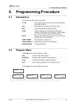
5.  Programming Procedure 


46 

HYDROFLEX PLUS No. 30199906 Rev. No. 1.1 

2022-01 

5.3 

Show Program 

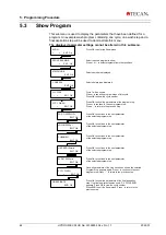
This submenu is used to display the parameters that have been defined for a 
program. An example wash program containing one cycle, one wash step and a 
final aspiration step will be used to demonstrate this menu. 

The displayed parameter settings cannot be altered in this submenu. 


Selected plate type displayed 

Press OK to enter the Show menu. 

SHOW 

<          >       EXIT  OK 

1: GRE96ft 

                       EXIT  OK 

STRIP MODE 

                       EXIT  OK 

C1 CYCLE 

  -      +           EXIT  OK 

C1 P1  WASH 

  -      +           EXIT  OK 

Select required program to show. 
 Press + or 

– to select programs from other positions. 

PROG1: EXAMPLE 

 -          +       EXIT  OK 

Selected mode is displayed. 

Press OK to show the parameters of the program step.  
Press + to continue to the next program step;  
Press “- “ to return to the previous step. 

Cycle 1 will be shown.  
Press + to show the program steps of this cycle.  
Press OK to show the cycle number. 

POS: OVERFLOW 

                     EXIT  OK 

VOLUME 300µl 

                     EXIT  OK 

CHANNEL 1 

                     EXIT  OK 

H-SPEED 10mm/s 

                     EXIT  OK 

FL.RATE 300µl/s 

                     EXIT  OK 

C1 P1  WASH 

  -      +           EXIT  OK 

FIN.ASPIRATE 

  -                   END  OK 

Press OK to show the parameters of the final aspiration 
step. 

If no final aspirate step was used, “CX CYCLEEND” 

appears. Press OK to view the cycle number. 
Press END to exit the Show menu. Press - to return to the 
previous step. 

Press OK to continue to the next parameter  
of the selected program step.  

Once all parameters of the step have been shown the selected 
Program Step appears again. Press + to continue to the next 
program step; Press “- “ to return to the previous step. 

Press OK to continue to the next parameter  
of the selected program step.  

Press OK to continue to the next parameter  
of the selected program step.  

Press OK to continue to the next parameter  
of the selected program step.  

Press OK to continue to the next parameter  
of the selected program step.  


Summary of Contents for HYDROFLEX

Page 1: ...Instructions for Use for HYDROFLEX PLUS Document Part No 30199906 2022 01 Document Revision No 1 1 Firmware Level 4 22...

Page 2: ...Prior to contacting Tecan for product support prepare the following information for the best possible technical support see name plate Model name of your product Serial number SN of your product Softw...

Page 3: ...0 F 43 6246 72 770 www tecan com E mail office austria tecan com Copyright Information The contents of this document are the property of Tecan Austria GmbH and are not to be copied reproduced or trans...

Page 4: ...ed trademark of Invitrogen Corporation Carlsbad CA USA Lysetol and Gigasept Intru AF formerly Lysetol are registered trademarks of Sch lke Mayr GmbH Norderstedt Germany Microcide is a registered trade...

Page 5: ...ield Consult instructions for use CE conformity marking United Kingdom Conformity Assessed marking shows that the labeled product is following the applicable regulation in Great Britain Catalogue numb...

Page 6: ...ILITY OF SEVERE PERSONAL INJURY LOSS OF LIFE OR EQUIPMENT DAMAGE IF THE INSTRUCTIONS ARE NOT FOLLOWED WARNING THIS SYMBOL INDICATES THE POSSIBLE PRESENCE OF BIOLOGICALLY HAZARDOUS MATERIAL PROPER LABO...

Page 7: ...otechnical Commission IFU Instructions for Use in Inch inHg Inches of mercury IVD In vitro diagnostics IVD D In Vitro Diagnostics Directive IVDR In Vitro Diagnostic Regulation IVDR EU 2017 746 kg Kilo...

Page 8: ...ments 25 3 2 Unpacking and Inspection 25 3 2 1 Unpacking and Inspection Checklist 26 3 3 Installation Procedure 27 3 3 1 Connection Diagram 28 4 Operating Instructions 29 4 1 Switching the Instrument...

Page 9: ...very Six Months 66 8 5 4 Yearly Service Engineer Required 66 8 6 Replacing the Manifold 66 8 6 1 General Description of the Manifold 67 8 6 2 Removing the Manifold 68 8 6 3 Installing the Manifold 69...

Page 10: ......

Page 11: ...v shaped bottom microplates in 96 well format typically used for EIA which conform to the standard defined by the Society of Biomolecular Screening Other plate types in 96 well format such as deep wel...

Page 12: ...D LEVEL OF THE WASTE BOTTLE IS ALWAYS KEPT BELOW THE MAXIMUM LEVEL INDICATED ON THE BOTTLE TO AVOID POTENTIAL OVERFLOW AS THE CONTENTS OF THE WASTE BOTTLE ARE POTENTIALLY INFECTIOUS WEAR PROTECTIVE CL...

Page 13: ...TE BOTTLE NOT PROVIDED WITH THE HYDROFLEX PLUS AND ADDITIONALLY INCREASE THE CONCENTRATION OF ANTI FOAMING AGENT IN THE WASTE BOTTLE TO HELP FACILITATE BREAKDOWN OF THE FOAM IN THE WASTE BOTTLE CAREFU...

Page 14: ......

Page 15: ...DING TO THE INSTRUCTIONS GIVEN IN THIS IFU AS WELL AS THE LIQUID COMPOUNDS USED REAGENTS WASH BUFFER CHEMICAL COMPONENTS THE INSTRUCTIONS FOR USE STORAGE AND OTHER HANDLING IN CONNECTION WITH SAMPLES...

Page 16: ...on 2 2 2 Principle of Operation The HYDROFLEX PLUS can be used to wash plates for a variety of test routines mainly in ELISA applications The HYDROFLEX PLUS is a microplate strip washer for automated...

Page 17: ...he person is able to recognize and avoid dangers Computer application skills and good language skills for the respective national language at the installation site and English are required Service Tec...

Page 18: ...l microplates and may vary using other 96 well plates or 96 well strip plates The table below lists the specifications for the instrument All specifications listed below are based on the following ins...

Page 19: ...ration 8 way manifold aspiration rate 3 aspiration time 4 s head speed 10 mm s wash buffer Residual volume of 5 l well cannot be guaranteed if a 16 way manifold is used and if not all wells are filled...

Page 20: ...199906 Rev No 1 1 2022 01 2 4 Instrument Description The diagram below shows the main components of the instrument Keyboard and Display Unit Manifold Arm Manifold Prime Tray Plate Support Guide Bar Po...

Page 21: ...al 2022 01 HYDROFLEX PLUS No 30199906 Rev No 1 1 21 2 4 1 Instrument Dimensions Standard Instrument Dimensions 203 mm 7 99 290 mm 11 42 362 6 mm 14 28 275 2 mm 10 83 365 8 mm 14 40 88 5 mm 3 48 180 5...

Page 22: ...ending on the specific model For an overview of the various instruments for which these Instructions for Use are valid see the Declaration of Conformity on the last page of this document All connected...

Page 23: ...LUS Option The HYDROFLEX PLUS can be delivered with the following option Liquid Level Detection LLD The level of liquid is checked in the liquid bottle s and in the waste bottle An acoustic signal ale...

Page 24: ...one waste bottle Fig 2 1 Waste and Liquid Bottles with LLD Sensors See chapter 3 3 1 Connection Diagram for further details 2 6 Microplate Requirements Only 96 well format microplates round v shaped...

Page 25: ...owed the dispensing pump must be recalibrated by a service technician For information regarding outer dimensions and weight of the instrument see chapter 2 3 Instrument Specifications 3 1 2 Power Requ...

Page 26: ...ns 6 Manifold screws and Allen key Main power cable 2 Cleaning needles 1 2 or 4 Solution tube s 1m depending on instrument configuration USB cable Bottle set containing 1 2 or 4 Liquid bottle s 2 5 li...

Page 27: ...ECTOR ON THE BACK PANEL OF THE INSTRUMENT THE WASH PERFORMANCE CAN BE SERIOUSLY AFFECTED Connect the solution tubes L1 L4 to the inlet connectors on the rear panel of the instrument see 3 3 1 Connecti...

Page 28: ...emote Control using the HydroControl software Maximum filling level as indicated on bottle USB Liquid 2 Liquid 1 Liquid 3 Liquid 4 Waste W L1 L2 L3 L4 L1 L2 L3 L4 W VAF LLD Sensors Liquid Tubes Waste...

Page 29: ...oControl software If a Rinse procedure was aborted before the instrument was switched off the following message is displayed after the instrument initializes PLEASE RINSE OK Press OK and then select a...

Page 30: ...ing amplitude of 1 mm o Medium Linear shaking with a shaking frequency of 10 Hz and a shaking amplitude of 2 mm o Low Linear shaking with a shaking frequency of 5 Hz and a shaking amplitude of 3 mm Ad...

Page 31: ...O Cycle number CYCLE NO Cycle number DEFINE EDIT Define Edit DISPENSE Dispense DISPENSE POS Dispense position EDIT LLD CHANNEL Edit LLD channel DISPLAY Meaning EDIT PLATES Edit plates EMPTY BOTTLES Em...

Page 32: ...1 Set channel 1 SET CHANNEL 2 Set channel 2 SET CHANNEL 3 Set channel 3 SET CHANNEL 4 Set channel 4 SET VAC WASTE Set vacuum waste SET WASTE 1 Set waste 1 SETTINGS Settings DISPLAY Meaning SHAKE HIGH...

Page 33: ...rating procedure is dependent on the instrument options and the program settings CAUTION BEFORE WASHING PROCEDURES ARE STARTED MAKE SURE THAT THE MICROPLATE POSITION A1 IS INSERTED CORRECTLY CAUTION B...

Page 34: ...imultaneous aspiration and dispense step It creates a circular flow of wash buffer in the well and ensures that the topmost parts of the well are also washed Bottom For ELISA assays Custom Any necessa...

Page 35: ...eedles are set at two positions on the bottom of the wells front edge and back edge Aspirate Y Offset 1 Aspirate Y Offset 2 Front edge Back edge Fig 4 5 Crosswise Aspiration for Flat Bottom Wells WARN...

Page 36: ...n the Define Edit menu see 5 2 2 Define Edit a Program Define Edit Menu for further information about defining programs Note The following example program should not be used as a standard wash procedu...

Page 37: ...the next parameter Select PROGRAM END and press OK Set the volume to 450 l and press OK to continue to the next parameter set the channel to 1 and press OK to continue to the next parameter Set the he...

Page 38: ...tube into a bottle containing distilled water 2 Use the Rinse Night rinsing procedure to rinse the wash system see chapter Rinse Night on page 59 3 When the rinsing procedure is completed the followi...

Page 39: ...l in one wash step for increased wash efficiency SOAK During a soak step the liquid remains in the wells for the set time with or without shaking USER PROMPT User interaction is requested FINAL ASPIR...

Page 40: ...ifold Depending on the type of manifold 1 or 2 strips at a time can be selected Press Chg to switch between selected and not selected Select the required strips using the cursor keys selected strips a...

Page 41: ...ect the number of cycles cycles can be repeated up to 9 times C1 P1 ASP EXIT OK Press or to select the process step ASP DISP WASH SOAK USER PR Press OK to define the selected process step Once the pro...

Page 42: ...osition BOTTOM OVERFLOW or CUSTOM Select required aspirating rate 1 3 where 1 is the weakest and 3 the strongest rate After the process step has been defined the initial display appears CX Cycle Numbe...

Page 43: ...EXIT OK Z POS OVERFLOW EXIT OK Select required flow rate drip to 500 l sec After the process step has been defined the initial display appears CX Cycle Number PY Program Step Number incremented by 1 P...

Page 44: ...d 50 3000 l in increments of 50 l Select and confirm wash step WASH CX Cycle Number PX Program Step Number Select required flow rate drip to 500 l sec Select required aspirating speed 1 20 mm sec Afte...

Page 45: ...IT OK TIME 0 min 10 s Chg OK SHAKE OFF EXIT OK The shaking speed can be selected OFF LOW MEDIUM or HIGH CX PY SOAK EXIT OK After the process step has been defined the initial display appears CX Cycle...

Page 46: ...ill be shown Press to show the program steps of this cycle Press OK to show the cycle number POS OVERFLOW EXIT OK VOLUME 300 l EXIT OK CHANNEL 1 EXIT OK H SPEED 10mm s EXIT OK FL RATE 300 l s EXIT OK...

Page 47: ...o be deleted from the instrument s memory Program Position Program Name The name of the program which has been deleted appears Program Name DELETED CLEAR EXIT OK CLR PROGR 1 NO YES A DELETED CLR PROGR...

Page 48: ......

Page 49: ...INGS OK OPTIONS EXIT OK BUBBLE SENSOR EXIT OK 6 1 1 Edit Plates EDIT PLATES EXIT OK Plate 1 GRE96ft EXIT OK Z User Def 14600 EXIT OK OVERFLOW POS EXIT OK Press OK to continue Press or to select the pl...

Page 50: ...ensor Press OK to activate LLD sensor for Vacuum Waste CLR VAC WASTE will appear when the sensor is active Press OK again to deactivate Press to move to the next sensor Press OK to activate LLD sensor...

Page 51: ...ime Start prime procedures Empty Prime Tray Aspirate liquid out of the prime tray The Procedures menu has the following structure PRIME EXIT OK PROCEDURES OK RINSE EXIT OK EMPTY PRIME TRAY EXIT OK 6 2...

Page 52: ......

Page 53: ...e of microplate or strip plate used see chapter 6 Settings Menu of this manual Necessary Tools Calibrated lab balance including cover for wind protection capable of reading milligrams Greiner F 96 wel...

Page 54: ...same height on a vibration free surface according to the manufacturer s guidelines Record serial number of lab balance and the HYDROFLEX PLUS used as well as name of operator for documentation purpos...

Page 55: ...bove tests perform thorough cleaning step using RINSE NIGHT procedure see Rinse Night on page 59 2 Disinfect manifold according to procedure described in chapter 8 8 Instrument Disinfection of this ma...

Page 56: ......

Page 57: ...e Day if the instrument will be left to stand for a short time up to two hours When Rinse Day is selected a Time how long the instrument rinses before the manifold is soaked in the prime tray can also...

Page 58: ...IT OK WASTE BOTTLE OK YES RINSE SOLUTION OK YES Confirm that the rinsing solution and the tube are in the bottle Select and confirm RINSE DAY procedure Select required channel 1 4 depending on instrum...

Page 59: ...lect and confirm RINSE NIGHT procedure Select the required channel 1 4 depending on instrument configuration Press OK and the wash system is rinsed Confirm that the waste bottle is empty The prime tra...

Page 60: ...rom the system For this purpose remove all tubes from the liquid bottles WARNING BEFORE THE INSTRUMENT IS USED ALL DISPENSING CHANNELS NEEDED FOR THE WASH PROGRAM MUST BE PRIMED TO FILL THE LIQUID SYS...

Page 61: ...IME SOLUTION OK YES Confirm rinsing solution and tube in bottle Select and confirm PRIME procedure Select required channel 1 4 depending on instrument configuration Select OK and the prime procedure s...

Page 62: ...with distilled water before the instrument is left to stand or switched off at the end of each day The manifold should be removed and thoroughly cleaned at least once every six months or whenever one...

Page 63: ...ng the Manifold 5 After the manifold has been cleaned switch the instrument on and perform the priming procedure using distilled water CAUTION IF ADDITIONAL CLEANING IS REQUIRED USE THE DELIVERED CLEA...

Page 64: ...Spilling of liquid or foam may occur when the HYDROFLEX PLUS is operated improperly such as 1 Used microplate not matching installed manifold 2 Positions of the strips in the strip plate do not match...

Page 65: ...INSTRUMENT AND DISCONNECT IT FROM THE MAIN POWER SUPPLY 8 5 1 Daily 1 Prime the liquid system if necessary 2 Perform Rinse Day with distilled water or wash buffer if the instrument is left to stand f...

Page 66: ...ely if they become clogged with particles or crystals 8 5 4 Yearly Service Engineer Required The yearly maintenance is performed by the service engineer 8 6 Replacing the Manifold WARNING AFTER THE IN...

Page 67: ...the manifold already installed The instrument can be used with the following types of manifolds Standard 8 way and Standard 16 way The manifolds for the HYDROFLEX PLUS have the same basic components F...

Page 68: ...onths or whenever needles become blocked 1 Lift the manifold arm and remove the black manifold arm guard plate by sliding it out from behind the three screws the screws do not need to be removed to pe...

Page 69: ...ERFORMING CLEANING PROCEDURES AND ALSO WHEN MAKING ADJUSTMENTS TO THE INSTRUMENT The standard manifolds are installed using the following procedure 1 Lift the manifold arm 2 Carefully fit the manifold...

Page 70: ...NTAMINATION WHEN PERFORMING CLEANING PROCEDURES AND ALSO WHEN MAKING ADJUSTMENTS TO THE INSTRUMENT The instrument is delivered with the plate carrier already installed If the plate carrier is removed...

Page 71: ...the instrument is thoroughly disinfected before it is removed from the laboratory or any servicing is performed on it Before the instrument is returned to the service center for service or repair it m...

Page 72: ...ve bag for all disposables used during the disinfection procedure label it with autoclave tape and put it in the autoclave or follow the procedure defined in chapter 8 9 3 Disposal of Operating Materi...

Page 73: ...rformed in a well ventilated room by authorized and trained personnel wearing disposable powder free gloves protective glasses and protective clothing The disinfection procedure should be performed ac...

Page 74: ...S ASSOCIATED WITH THE TREATMENT OF ELECTRICAL AND ELECTRONIC EQUIPMENT WASTE DO NOT TREAT ELECTRICAL AND ELECTRONIC EQUIPMENT AS UNSORTED MUNICIPAL WASTE COLLECT WASTE FROM ELECTRICAL AND ELECTRONIC E...

Page 75: ...RIATE COLLECTING POINTS AND APPROVED METHODS OF DISPOSAL IN YOUR COUNTRY STATE OR REGION 8 9 4 Disposal of the HYDROFLEX PLUS Please contact your local Tecan service representative before disposing of...

Page 76: ......

Page 77: ...1 Standard Instrument Error Messages Plate Error If the plate sensor does not recognize the plate or no plate is inserted on the plate carrier the following message is displayed NO PLATE OK Press OK a...

Page 78: ...is defective SENSOR DEFECT OK Press OK to remove the error message and to return to the standby mode Make sure that drip mode has not been selected using distilled water Change the program parameters...

Page 79: ...RECOMMEND SWITCHING TO A LARGER WASTE BOTTLE NOT PROVIDED WITH THE HYDROFLEX PLUS AND ADDITIONALLY INCREASE THE CONCENTRATION OF ANTI FOAMING AGENT IN THE WASTE BOTTLE TO HELP FACILITATE BREAKDOWN OF...

Page 80: ......

Page 81: ...30 I Installation Procedure 27 Installing the Manifold 69 Instrument Description 20 Disinfection 71 Disposal 74 Firmware 30 Safety 11 Specifications 18 Switching on 29 Instrument Options 23 Intended...

Page 82: ...7 Night 57 Rinsing 57 S Safety 11 Settings Menu 49 Show Program 46 Soak 45 Spills 64 Starting a Program 40 T Trouble Shooting and Error Messages 77 U Unpacking and Inspection Checklist 26 Unpacking an...

Page 83: ......

Reviews: