6
External sensors connection
The shock sensor included in the delivery kit is equipped with dedi-
cated outputs for warning and alarm� This sensor operates correctly
in both multiplex and standard modes� Sensor connection is carried
out with a special harness supplied in the kit� No additional program-
ming is required�
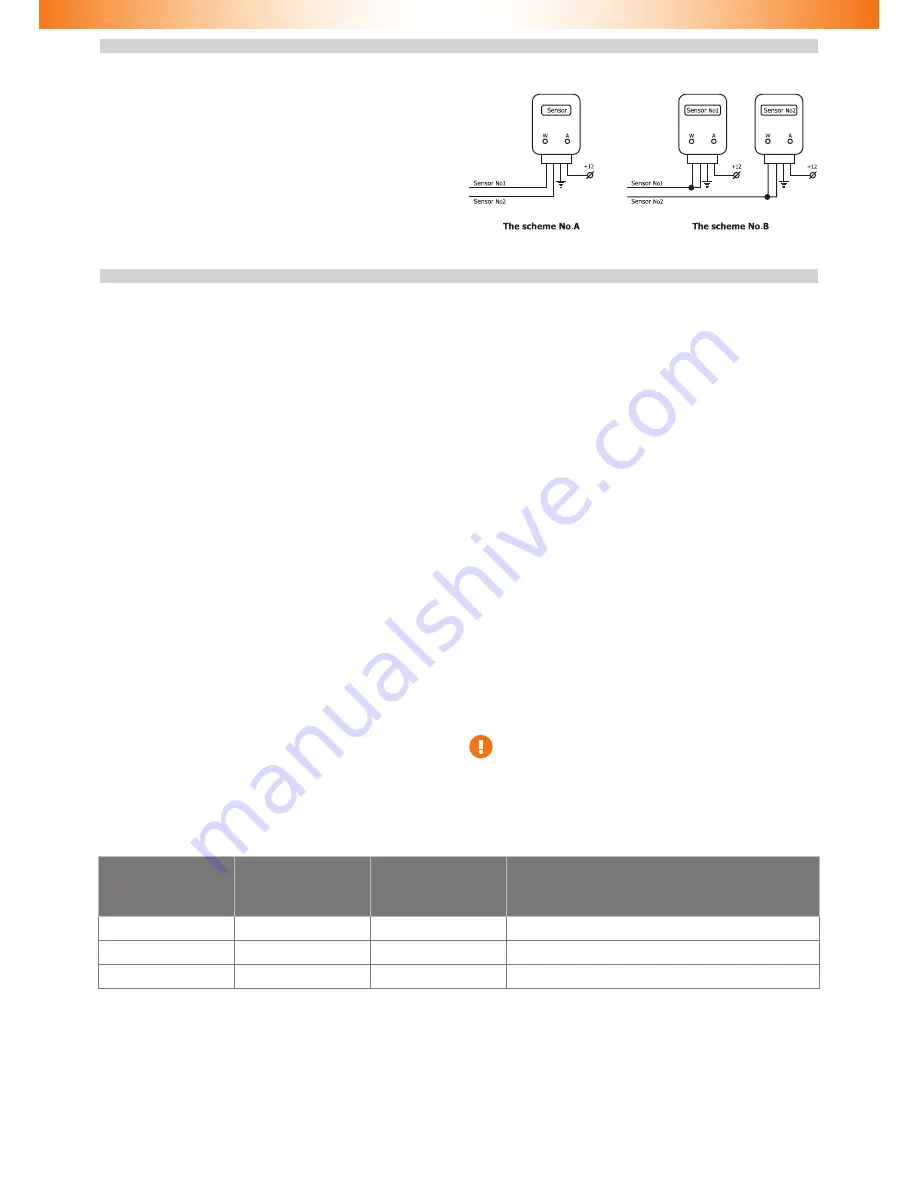
When it is necessary to install other sensors, various connection
schemes are available, two of which are presented below�
Should the sensor with dedicated warning and alarm zones please
refer to Scheme No� A� It is necessary to use the standard sensors op-
eration mode (see Alarm hardware features programming (Menu 1)
section)� In this scheme Sensor No� 1 has a functional purpose of
warning input, while Sensor No� 2 is the triggering input�
When connecting two multiplex sensors Scheme No� B is applied� In
this case it is necessary to program the multiplex sensors inputs oper-
ation (see Alarm hardware features programming (Menu 1) section)�
In this scheme functional purposes of sensor inputs are identical�
When receiving a signal longer than 0�8 sec, Warning is triggered� If
the signal is longer than 0�8 sec, Alarm is activated�
Alarm programming
Alarm programming is carried out with Programming button
Programming stage one. Alarm interfacing with the vehicle
Identifying the vehicle model
Vehicles supported by the Alarm are divided into functional groups,
each of which is divided into subgroups� All groups and subgroups
are assigned with item ordinals (see Integrator files). Interfacing
is the procedure of Alarm detecting vehicle group and subgroup�
There are two interfacing options:
1
Automatic interfacing
In order to automatically interface the Alarm with the vehicle it is
necessary to carry out a set of actions (see Integrator files). Upon
vehicle identification algorithm is launched the Alarm emits a con
-
stant audible signal�
If the Alarm identifies only the vehicle group, then it will stop emit
-
ting the constant signal and will periodically emit series of audible
and light signals, where the number of signals will correspond with
the group number�
If the Alarm identifies both the group and subgroup of the vehicle,
then it will inform on the completion of vehicle interfacing with an
audible sound trill and will emit three series of audible and light sig-
nals where the number of long signals corresponds with the group
number and the number of short signals corresponds with the sub-
group number�
2
Forced interfacing
This algorithm is used in extraordinary cases�
Programming is carried out with the integrated Programming but-
ton� Prior to interfacing procedure initiation vehicle group must not
be identified and CAN bus must not be connected. Programming will
stop if Programming button shall not be pressed within 60 seconds�
Programming sequence:
2�1
Power the Alarm and wait for discontinuous audible and
light signal�
2�2
Enter Menu 1 by pressing and releasing the Programming
button 10 times (this needs to be done no later than 10
seconds after the system has been powered)� If the proce-
dure is carried out correctly, the Alarm will inform on this
fact with three audible and light signals�
2�3
Enter menu option No� 1 – Vehicle model – by pressing the
Programming button once� The Alarm will inform on option
condition with 1 audible and 1 light signal series�
2�4
Enter the vehicle’s group number by pressing the Program-
ming button for the corresponding number of times (see
Integrator files). The Alarm will periodically emit series of
audible and light signals where the number of signals cor-
responds with the group number�
2�5
Enter the vehicle’s subgroup number by pressing the Pro-
gramming button for the corresponding number of times
(see Integrator files).
Verify that the vehicle model has been chosen correctly with help
of audible and light signals (group number – pause, subgroup num-
ber – pause):
◊
If the vehicle model has been chosen correctly, press the Pro-
gramming button once� Audible and light signals will stop and
the vehicle model will be programmed�
◊
If the vehicle model has been chose incorrectly, then press the
Programming button twice� Repeat the programming proce-
dure beginning from p� 2�4�
Analog steering wheel buttons programming
In order to use the analog steering wheel buttons please do as
follows:
◊
• Right after the Immobilizer identifies the vehicle model,
turn the ignition on and wait for no less than 5 seconds�
◊
• Press all the steering wheel and steering wheel column
joysticks’ buttons (cruise control, central unit control etc�) se-
quentially (one after another)� The buttons, upon pressing of
which and audible signal will be heard and a light signal will be
seen, are available for use�
◊
• Turn the ignition off; an audible sound trill will be played.
◊
• Turn the ignition on.
◊
• Assign the Programming button from available ones by
pressing and holding it for no less than 5 seconds (until an
audible signal will be heard)�
It is necessary to initiate steering wheel analog button within
15 minutes since the Alarm interfacing with the vehicle� If
more than 15 minutes has passed please revert the settings
back to factory default and reprogram the Alarm�
Programming stage two. Alarm configuration programming
At stage two Alarm hardware functions and user settings are changed and a new PIN code is programmed� Three independent menus are
used during programming (see Programming menu table)�
Table 6� Programming menu
Name
Menu entering code
Audible signals number
Function
Menu 1
10
3
Alarm hardware settings configuration
Menu 2
12
4
Alarm user settings configuration
Menu 3
14
1
PIN code changing


