13.11 Wheel Nuts
Before using a new machine and daily during use, check
the wheel nuts are tight. They should be torqued to a
value of 400Nm (320 lb ft).
Once the nuts are allowed to work loose, it may be
found impossible to keep them tight and new nuts and
studs will be required to overcome the problem. In
extreme cases, damage to the wheel rims and hubs
may result.
13.12 Tyre Pressure
Check the tyre pressures regularly inflating them to the
pressures in table 3 overleaf as required.
Table 3. Tyre Pressures
13.13 Replacing Wheels
If it is necessary to remove a wheel, place a jack
underneath the axle beam, loosen the wheel nuts
and raise the machine until the wheel can be removed.
Place an axle stand underneath the machine
before removing the wheel. Refit the wheel and
tighten the wheel nuts.
13.14 Electric Controls.
The electric controls require no maintenance and it is
imperative that no part of the system is ever sprayed
with a moisture repelling agent such as WD40.
If a malfunction of the system occurs, please contact
Teagle Machinery Ltd or an authorised dealer/distributor
for advice.
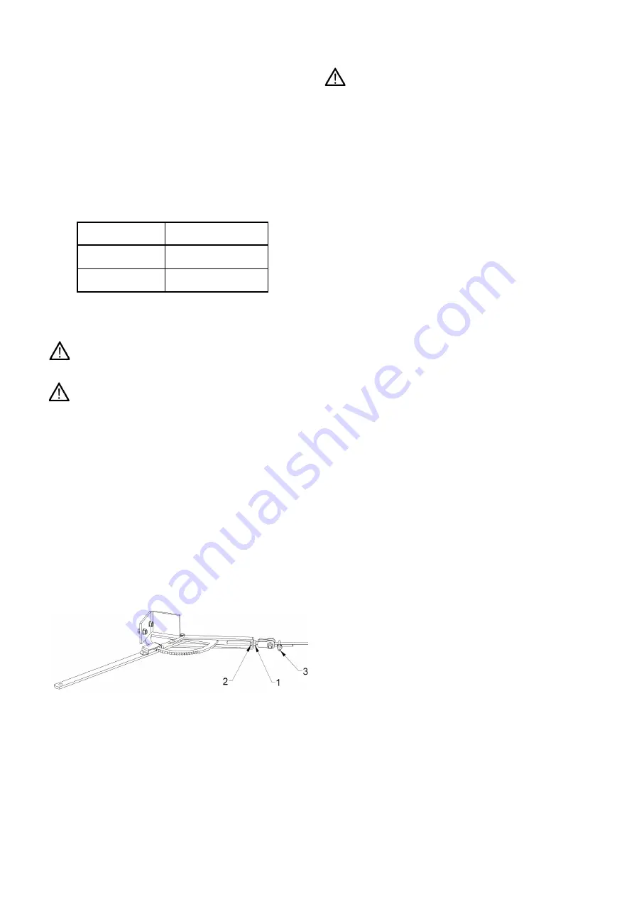
13.15 Handbrake Adjustment
With reference to figure 8 below, the handbrake can be
adjusted by releasing the locknut (item 1) and increasing
tension by means of the tension nut (item 2). If
maximum travel is reached then the clamp (item 3) can
be released and the rope adjusted accordingly.
Figure 8. Handbrake Adjustment
13.16 Service Brake Adjustment
It is imperative that the brakes are adjusted
correctly to meet the requirements of the current
braking regulations. As the brake shoes wear, it may be
necessary to realign the actuating rods on their splines
so that the arms are perpendicular to the ram body.
13.17 Removal Of Main Rotor
The rotor can only be released from the main gearbox
with the application of service tool SC3776 available
from the manufacturer.
14. OPTIONAL EXTRAS
14.1 Drawbar Jack
Where the machine is fitted with a drawbar jack, adjust
the height of the drawbar to match the height of the hitch
point on the tractor. Reverse the tractor and attach the
drawbar. Lower the machine until the weight is fully
transferred to the tractor. Remove the pin retaining the
jack to the drawbar and transfer it onto the transport
position across the front of the chassis.
15. MACHINE STORAGE
When the machine is not being used it is
recommended that the control box be stored safely
away from the machine in a dry location. The electrical
connections together with hydraulic hoses should be
stored in the positions provided on the layshaft guard
on the front right of the machine. If the machine is to
be laid up for any great length of time it should be
thoroughly cleaned down and any bright surfaces
treated with paint as opposed to a rust preventative
since the machine is used for dispensing foodstuffs. All
lubrication points should be attended to ready for
subsequent reuse.
16. DISPOSAL
At the end of the machine’s working life, the method of
disposal must be within the legislation laid down by the
local authority or the National Environment Agency.
The machine is composed of ferrous materials,
synthetic paints and rubber compounds.
10
Tyre Size
Pressure bar (psi)
285/70R19.5
5.8 ( 84)
405/60 R22.5
5.8 ( 84 )
Summary of Contents for Tomahawk 1010
Page 1: ......
Page 38: ...34 HYDRAULIC HOSES...
Page 43: ...WIRING DIAGRAM LIGHTS WIRING DIAGRAM TRACTOR LEAD 39...
Page 44: ......


