13.5 Gearbox
After 50 hours of use the gear box oil should be drained
and replaced with new oil. To drain the oil, remove the
PTO shaft and guard cone remove the drain and filler
plugs and allow it to empty. Waste oil should be
collected and disposed of at an oil recycling facility
Refill the gearbox to the level plug with SAE90.EP
gearbox oil. The oil capacity of the gearbox is 4.7ltrs
13.6 Drive Chains
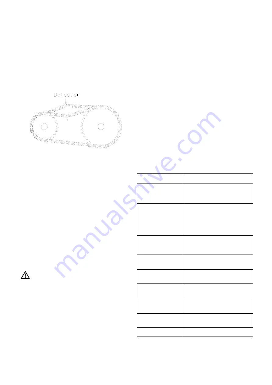
Apply chain lubricant or oil weekly. The chains should be
tensioned so that there is 12-13mm (1/2”) deflection at
the mid span point as indicated in figure 7 below.
Figure 7. Chain Deflection
To tension the crossbeaters drive chains, open the
hinged chain guard on the left hand side of the
machine
.
For the lower beater drive, slacken the
layshaft bearing bolts and tensioner locknut. Increase
tension by jacking the bearing as required until the
correct tension condition is met. Retighten all nuts. For
the upper crossbeater slacken the tensioner roller
mounting bolt in the centre of the roller and turn the
tension screw on the adjuster clockwise until the
correct tension condition is met. Retighten the roller
mounting bolt.
13.7 Swivel Chute
The chute is rotated by means of a gear and ring gear.
It is important that this is well greased. To apply grease
to the ring gears there are 4 grease nipples on the
mounting flange.
The deflector ram has 2 grease nipples, one on each
pivot bush.
13.8 Hydraulics
Before attempting to dismantle any of the hydraulic
system, the tailgate and deflectors must be fully
lowered to prevent injury from the unexpected lowering
of these components.
The hydraulic system is protected from contamination by
an inline pressure filter. Periodically the element should
be checked for contamination and it is recommended
that the element be replaced at least once annually. To
replace the element, remove the guard covering the
hydraulic valve on the front right of the machine and
unscrew the filter canister. Replace element, retighten
canister and fit valve guard.
If problems are experienced with either the hydraulic
system or electric controls, please contact Teagle
Machinery Ltd. for advice as a separate manual is
available to cover troubleshooting and repair.
13.9 PTO Slip Clutch
If the clutch slips repeatedly for no apparent reason
there are a number of things to be checked:
Firstly check that the clutch linings do not show signs of
damage or excessive wear. If so, they should be
replaced. When new they are 3mm. (1/8") thick.
Also make sure that the compressed spring length is set
to give the correct torque setting – see PTO shaft parts
list.
If the clutch continues to slip it should be adjusted as
follows:
1 Remove the guard fitted to the rotor gearbox.
2 Fit the PTO shaft with the slip clutch at the machine
end.
3 Insert a piece of wood through the discharge chute
and position it such that it prevents the rotor from
turning.
4 Insert a steel bar through the rear PTO yoke and use
a spring balance to obtain the correct torque setting.
The clutch should just slip at a torque of 1200 Nm.
(900 lb.ft.) - equal to a force of 1000N. at 1.2 metre
(225 lb. at 4 feet) from the centre of the yoke. Adjust
the clutch as necessary using the eight spring loaded
clamp bolts.
13.10 Lubrication
Good quality semi-solid grease should be applied to the
following grease points:
The above lubrication frequencies are based on typical
daily use for bedding & feeding purposes. Continuous
use for special applications may require more frequent
lubrication.
9
Greasing / Oil
See separate Chart
PTO and clutch
Lubricate as Chart
Dismantle Clutch at Start of
Season
Gearboxes
Replace main gearbox oil after
first 50 hours then check
monthly. Where fitted, check
bed chain drive gearbox
monthly
Remove stones
Each Bale Or Daily,
Depending On Use And Na-
ture Of Bales
Bed Chain
Tension
After First Day Then
Weekly Depending On Use
Crossbeater Chain
Tension
Weekly
Clean above
inspection Panel
Monthly, Depending On Use
Tyre pressures &
Wheel nuts
Monthly
Option – Replace
oil filter
Yearly
Blades
As Required
Summary of Contents for Tomahawk 1010
Page 1: ......
Page 38: ...34 HYDRAULIC HOSES...
Page 43: ...WIRING DIAGRAM LIGHTS WIRING DIAGRAM TRACTOR LEAD 39...
Page 44: ......


