


INSTRUCTION MANUAL
GXE600 Series
TDKLambda
<Page>
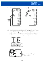
618. Communication Configuration Switch (SW81)
If the communication configuration (Slave ID, Baud Rate, Parity, Other) is unknown and the communication
function is unusable, reset the configuration as follows. The startingup with default configuration is possible by
SW81.
The SW81 is set at
“
ENABLE
”
side at time of shipment.
Step 1
:
After the AC shut down and cool down the product, set the SW81 to
“
DISABLE
”
side.
Step 2
:
After input the AC, read the communication configuration registers by communication function.
Step 3
:
Modify the communication configuration registers as necessary.
Step 4
:
After the AC shut down and cool down the product, set the SW81 to
“
ENABLE
”
side.
Refer to
“
Communication Manual
”
for details.
Do not touch this product or its internal components while circuit in operation, or shortly after shutdown.
You might receive a burn.
*/A : For the option model with cover,
slide the SW81 from the rectangle hole at side surface
by non conductive tweezers etc..
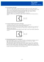
619. Communication Function (RS485)
Communication function is provided. The physical layer is RS485 and the protocol supports MODBUS.
Refer to
“
Communication Manual
”
for details.
<Communication function example>
・
Various monitoring function
(Output voltage, Output Current, Converter operation time, Internal temperature)
・
Protection history (OCP, OVP, OTP, etc.)
・
Protection configuration (Threshold value, Protection mode auto recovery or latch)
・
Remaining lifetime of the electrolytic capacitor calculation.
・
Real time control of PV reference and CC reference
・
Slew rate of the output voltage and current adjustment.
・
Remote ON/OFF control and its configuration (CNT mode and CNT terminal input sensitivity)
・
Communication configuration (Slave ID, Baud Rate, Parity, Other)
・
Product information indication (Model name, Serial No., Lot No., Firmware ver.)
・
Scratch Pad (Up to 30 characters of data can be stored in ASCII characters. )
19/28
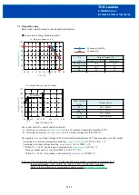
Item
Default Setting
Slave ID
1
Baud Rate
19200 bps
Parity
Even paryty
Other
Start : 1 bit / Stop : 1 bit / LSB First
Communication Configuration Swtch (SW81)
ENABLE
DISABLE


