


INSTRUCTION MANUAL
GXE600 Series
TDKLambda
<Page>
6. Explanation of Functions and Precautions
61. Input Voltage Range
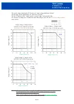
Input voltage range is single phase 85265VAC (4763Hz). DC input is inhibited.
Input voltage, which is out of specification, might lead unit damage. For cases where conformance to various
safeties required, described as 100240VAC (5060Hz). Output derating is required for AC input voltage less
than 170VAC.
* GXE is able to withstand input of 300VAC for 5 seconds (No damage). The electrical characteristics
are satisfied at within 85265VAC.
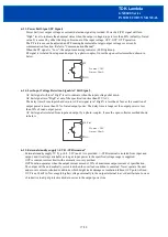
62. Output Voltage Range
Output voltage is set at the nominal voltage at time of shipment. Output voltage can be adjusted by the
output voltage adjustment trimmer (+/20% of nominal). The output voltage must be within specification.
Turning the trimmer clockwise, the output voltage will be increased. Take note when the output voltage is
increased excessively, over voltage protection (OVP) function might operate.
It is also possible to adjust the output voltage by PV function. Refer to
“
612. External output voltage control
(PV)
”
Furthermore, when the output voltage higher than nominal voltage, the output current must be reduced as not
to exceed the maximum output power.
63. Inrush Current
The switch method is used for limiting the inrush current. Higher current might flow when input turn on
interval is short.
First inrush current and second inrush current flow. Select input switch and external fuse carefully.
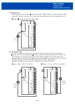
64. Over Voltage Protection (OVP)
GXE has SWOVP and HWOVP.
・
SWOVP /S (remote sensing terminal) voltage. Adjustable OVP point by communication function.
(Default : 125% typ. of nominal output voltage.)
・
HWOVP detect +/V (output terminal) voltage. Not adjustable OVP point (120
~
130% of nominal output
voltage).
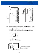
The OVP function is output shut down method and manual reset type. To reset OVP, remove the input of power
supply for a few minutes and reinput. Or, use Remote ON/OFF control reset (Remote : OFF to ON).
It is possible to change to automatic recovery method by communication function.
Never apply higher voltage externally to the output terminal to avoid unit failure. In case of inductive load, put
protective diode in series to the output power line.
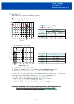
65. Over Current Protection OCP
GXE has SWOCP (adjustable OCP point by communication function.) and HWOCP (fixed OCP point).
And adjustable operation mode of SWOCP,
“
automatic recovery (default)
”
or
“
output shut down
”
by
communication function.
Therefore, OCP operation can be selected from the following.
・
Constant current limit and automatic recovery (Default)
:
[CC reference < SWOCP point]
OCP operation is constant current limit mode by CC function.
・
Hiccup mode
:
[CC reference
≧
SWOCP point, SWOCP mode :
“
automatic recovery
”
]
OCP operation is hiccup mode. Hiccup cycle is 1 second (adjustable).
・
Output shut down
:
[CC reference
≧
SWOCP point, SWOCP mode :
“
output shut down
”
]
OCP operation is output shut down mode. To reset OCP, remove the input of power supply for a few
minutes and reinput. Or, use Remote ON/OFF control reset (Remote : OFF to ON).
* HWOCP
HWOCP is output shut down mode and operates when abnormality such as output short circuit. To reset
OCP, remove the input of power supply for a few minutes and reinput. Or, use Remote ON/OFF control
reset (Remote : OFF to ON). HWOCP point and operation mode is fixed.
Never operate the unit under over current or shorted conditions, which might leads damage or insulation
failure. Refer to
“
Communication Manual
”
for CC reference and SWOCP for more information.
13/28


