83-517-000 Rev.
A
37
Table 4-1:
Front Panel Controls and Indicators (continued)
Number
Control/Indicator
Description
Section
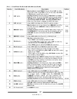
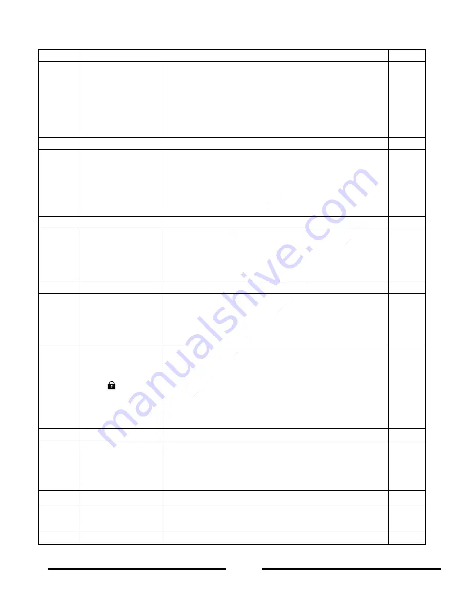
7
OUT
button
Main function:
Output
ON/OFF
control. Press
OUT
to set the
output ON or OFF. Press
OUT
to turn On the output after
OVP
or
FOLD
alarm events have occurred.
Auxiliary function:
Selects between “
Safe-Start
” and “
Auto-
Restart
” modes. Press and hold
OUT
button to toggle between
“
Safe-Start
” and “
Auto-Restart
”. The
VOLTAGE
display will
cycl
e between “
SAF
” and “
AU7
”. Releasing the
OUT
button
while one of the modes is displayed, selects that mode.
5.6
5.11
8
OUT
indicator
Green
LED
, illuminates when the DC output is enabled.
9
REM/LOC
button
Main function
: Go to Local mode. Press
REM/LOC
to put the
unit into Local mode (
REM/LOC
button is disabled at Local
Lockout mode).
Auxiliary function:
Address and Baud Rate setting. Press and
hold
REM/LOC
for 3 seconds to set the unit Address with the
VOLTAGE
encoder and the Baud Rate with the
CURRENT
encoder.
7.2.5
7.2.2
7.2.4
10
REM/LOC
indicator
Green
LED
, lights when the unit is in Remote mode.
11
FOLD
button
FOLD
back protection control.
- Press
FOLD
to set Foldback protection to
ON
.
- To release
FOLD
back alarm event, press
OUT
to enable the
output and re-arm the
FOLD
back protection.
- Press
FOLD
again to cancel the
FOLD
back protection.
5.5
12
FOLD
indicator
Green
LED
, lights when
FOLD
back protection is
ON
.
13
OVP/UVL
button
Over Voltage Protection and Under Voltage Limit setting.
- Press once to set
OVP
using
VOLTAGE
encoder (the current
display shows “
OUP
”)
- Press again to set the
UVL
using
VOLTAGE
encoder (the
current display shows “
UUL
”).
5.3
5.4
14
PREV
/
button
Main function:
Press
PREV
to display the Output voltage and
Output current limit setting. For 5 seconds the display will show
the
PREV
iew settings and then it will return to show the actual
Output voltage and Output current.
Auxiliary function:
Front Panel Lock. Press and hold
PREV
bu
tton to toggle between “Locked Front Panel” and “Unlocked
Front P
anel”. The display will cycle between “
LFP
” and “
UFP
”.
Releasing the
PREV
iew button while one of the modes is
displayed selects that mode.
5.17
15
PREV
indicator
Green
LED
, lights when the
PREV
iew button is pressed
16
FINE
button
Voltage and Current Fine/Coarse adjustment control. Operates
as a toggle switch. In
FINE
mode, the
VOLTAGE
and
CURRENT
encoders operate with high resolution and in
COARSE
mode with lower resolution (approximately 6 turns).
Auxiliary function:
Advanced Parallel Operation Mode Setting.
5.15.2
17
FINE
indicator
Green
LED
, lights when the unit is in
FINE
mode.
18
ALARM
indicator
Red
LED
, blinks in case of fault detection.
OVP
,
OTP
.
FOLD
back, Enable and AC fail detection will cause the
ALARM
LED
to blink.
19
AC Power switch
AC
ON/OFF
control.

