2800 LAURA LANE • MIDDLETON, WI 53562 • (800) 288-9383 • FAX (608) 836-9044 • www.tcsbasys.com
3
Note:
If using remote sensor(s), the calibration may
need to be adjusted. See “Checkout and
Troubleshooting” section.
TEMPERATURE SENSOR SELECTION
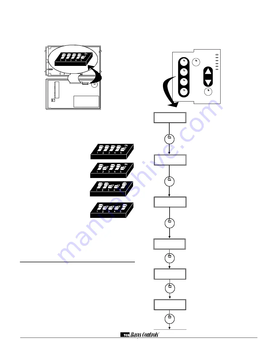
The dipswitches in the cover (shown above) must be set
when using remote room, and/or pipe temp sensors.
Use the following guide to determine the dipswitch set-
tings for your application.
Using built-in room sensor
only. (This is the default
setting.)
Using built-in room sensor
with pipe sensor only. (SZ1062
only)
Using remote room sensor
only.
Using remote room sensor
with pipe sensor only. (SZ1062
only)
Once the dipswitches have been set and you have con-
firmed that the sensors are reading correctly, secure the
cover to the base with the two set screws located at the
top right and the left side to prevent tampering.
Programming
The SZ1061 and SZ1062 may be programmed through
the keypad on the face, or with a PC.
If programming with a PC, the following must be set
through the face prior to programming:
• Address (step #10)
• Baud rate (step #11)
• Temperature scale (step #12)
For more information on programming through the PC,
consult your TCS software manual.
PROGRAMMING THROUGH THE KEYPAD
To access the programming screens, press the program
setup button. Screens A thru F are monitoring screens
and programming screens begin with #1. Access may be
locked out with dipswitches, or an access code may be
required.
program
setup
program
setup
BRANCH TO CLOCK/
2
.
SCH. MENU
?
YES
ENTER ACCESS
000
CODE
1
.
NO
OVERRIDE ON
178 MINUTES
F.
program
setup
E
.
program
setup
program
setup
PIPE TEMP:
D.
150F
DI3 OPEN
OFF
AUX RELAY
C.
program
setup
program
setup
DI
2
OPEN
DI
1
OPEN
B.
program
setup
A
.
WED FAN:MED
3:27 PM
82
F
STAGE
1
ON
STAGE
2
OFF
1 2 3 4 5
Main Monitoring Screen
. Press
the program setup button to access
the following screens.
Digital Input 1 & 2 Status Screen.
Shows the status of DI1& DI2.
Digital Input 3 Status & Auxiliary
Relay Output Screen.
Shows the
status of DI3. Shows the status of
the auxiliary relay output. This can
be either a timeclock output, a
stage of heat or a stage of cool.
(Aux. output on SZ1062 only)
Stage 1 & 2 Status Screen.
Shows
the status of stage 1 (heat) & stage
2 (cool).
Pipe Temperature Screen.
Shows
the pipe temperature if a pipe
temperature sensor is used
(SZ1062 only).
Override Status Screen.
Shows
the status of the first and second
stages of heating.
high
Occupied
Heating
Cooling
Data / Program
Service
COOLER
WARMER
Fan
fan
medium
fan
low
fan
fan
off
program
setup
OVERRIDE


