6-12
OPERATING PROCEDURES
Model C612
Operating Procedures
6
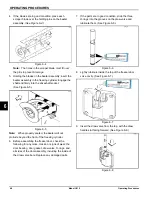
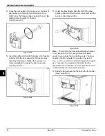
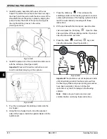
3. Install the pump assembly at the rear of the mix
hopper. To position the pump on the drive hub, align
the drive hole in the piston with the drive crank of the
driveshaft. Secure the pump in place by slipping the
pump clip over the collar of the pump, making sure
the clip fits into the grooves in the collar.
Figure 6-48
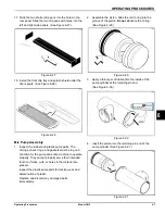
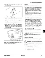
4. Install the pump end of the mix feed tube and secure
with the cotter pin. (See Figure 6-49.)
Important!
Failure to follow this instruction could
result in sanitizer spraying on the operator.
Figure 6-49
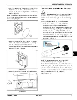
5. Pour the remaing pail of sanitizing solution into the
mix hopper.
6. Using the blue hopper brush, scrub the exposed
sides of the hopper. Install the agitatior blade onto the
agitator post.
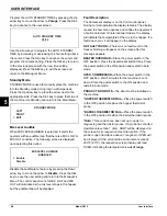
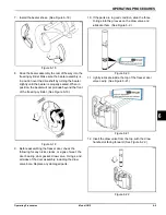
7. Press the Wash key
. This will cause the
sanitizing solution in the freezing cylinder to come in
contact with all areas of the freezing cylinder. Wait at
least 5 minutes before proceeding with these
instructions.
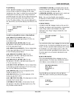
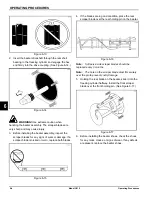
8. With a pail beneath the door spout, open the draw
valve and press the Pump key
. Open the draw
valve and draw off the sanitizing solution. Open and
close the draw valve six times.
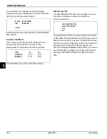
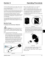
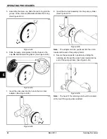
9. Press the Wash
and Pump
keys and
close the draw valve. (See Figure 6-50.)
Figure 6-50
Important!
The machine must not be placed in Auto
until all sanitizing solution has been removed from
the freezing cylinder and proper priming procedures
have been completed. Failure to follow this
instruction may result in damage to the freezing
cylinder.
Note:
Make sure your hands are clean and
sanitized before continuing these instructions.
30384_A
Summary of Contents for C612
Page 8: ...1 4 TO THE INSTALLER Model C612 To the Installer 1 Notes...
Page 54: ...9 2 PARTS REPLACEMENT SCHEDULE Model C612 Parts Replacement Schedule 9 Notes...
Page 58: ...10 4 LIMITED WARRANTY ON EQUIPMENT Model C612 Limited Warranty on Equipment 10 Notes...
Page 62: ...11 4 LIMITED WARRANTY ON PARTS Model C612 Limited Warranty on Parts 11 Notes...

