6-6
OPERATING PROCEDURES
Model C612
Operating Procedures
6
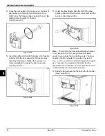
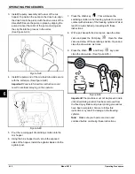
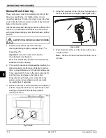
13. Place the door gasket into the groove on the back of
the freezer door. Slide the front bearing over the
baffle rod so the flanged edge is against the door.
Do
not
lubricate the gasket or bearing.
(See Figure 6-23.)
Figure 6-23
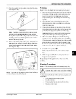
14. Insert the baffle rod through the beater in the freezing
cylinder. With the door seated on the freezer studs,
install the handscrews. Tighten them equally in a
crisscross pattern to ensure the door is secured.
(See Figure 6-24.)
Figure 6-24
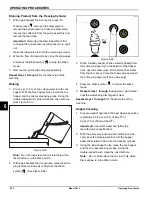
15. Install the draw handle. Slide the fork of the draw
handle in the slot of the draw valve. Secure it with the
pivot pin. (See Figure 6-25.)
Figure 6-25
Note:
This machine features adjustable draw handles
to provide portion control, giving a more consistent
quality to your product and controlling costs. The draw
handles should be adjusted to provide a flow rate of
5 oz. to 7-1/2 oz. (148 ml to 222 ml) of product by weight
per 10 seconds. To increase the flow rate, turn the
adjustment screw clockwise. Turn the adjustment screw
counterclockwise to decrease the flow rate.
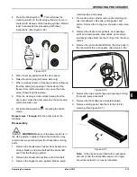
16. Slide the long drip pan into the hole in the front panel.
(See Figure 6-26.)
Figure 6-26
Summary of Contents for C612
Page 8: ...1 4 TO THE INSTALLER Model C612 To the Installer 1 Notes...
Page 54: ...9 2 PARTS REPLACEMENT SCHEDULE Model C612 Parts Replacement Schedule 9 Notes...
Page 58: ...10 4 LIMITED WARRANTY ON EQUIPMENT Model C612 Limited Warranty on Equipment 10 Notes...
Page 62: ...11 4 LIMITED WARRANTY ON PARTS Model C612 Limited Warranty on Parts 11 Notes...

