5-8
USER INTERFACE
Model C612
User Interface
5
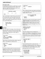
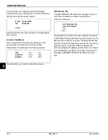
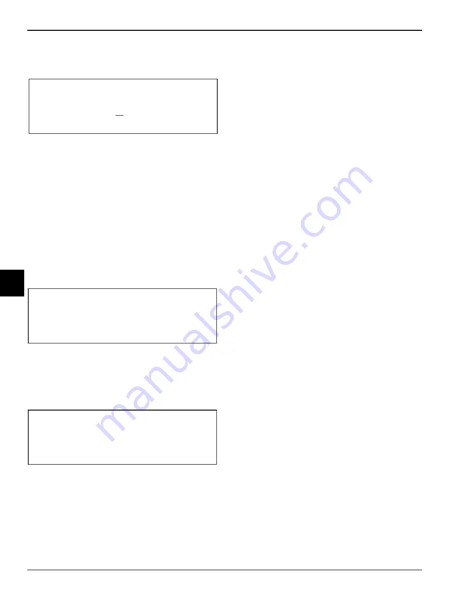
Program the AUTO STANDBY TIME by pressing the Up
arrow key to move the arrow to
Change
. Press the SEL
key to advance to the next screen.
Use the arrow keys to program the AUTO STANDBY
TIME by increasing or decreasing the hour setting above
the cursor. Press the SEL key to advance the cursor and
program the minutes setting. Press the SEL key to return
to the previous screen with the new time setting
displayed. Press the SEL key to exit the screen and
return to the Manager's Menu.
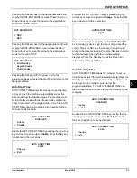
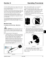
Standby Mode
STANDBY MODE is used to manually place the machine
into the Standby mode during long no-draw periods.
Press the Up arrow key to place the arrow next to the
appropriate side. Press the SEL key to place that side of
the machine into Standby and return to the Main Menu.
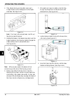
Mix Level Audible
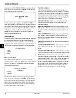
When MIX LEVEL AUDIBLE is selected, it alerts the
operator with an audible tone that there is a MIX LOW or
MIX OUT condition. The following screen is displayed
upon selecting this option:
Disable the audible tone feature by pressing the Down
arrow key to move the arrow to
Disable
. Press the SEL
key to save the new setting and return to the Manager's
Menu. The control panel icons for MIX LOW and MIX
OUT will illuminate as the mix level drops in the hopper,
but the audible tone will be disabled.
Fault Description
The fluorescent display is on the front control panel.
During normal operation the display is blank. The display
is used to show menu options and notifies the operator if
a fault is detected. On international models, the display
will indicate the temperature of the mix in the hopper. If a
fault does occur, it will appear on the display.
NO FAULT FOUND—
There was no fault found in the
freezer. Nothing will appear on the screen after this
message appears.
BEATER OVERLOAD—
Place the power switch in the
OFF position. Press the beater reset button firmly. Place
the power switch in the ON position and restart in Auto
mode.
HPCO COMPRESSOR—
Place the power switch in the
OFF position. Wait 5 minutes for the machine to cool
down. Place the power switch in the ON position and
restart in Auto mode.
PRODUCT DOOR OFF—
The door must be installed on
the machine.
*HOPPER THERMISTOR FAIL—
Place the power switch
in the OFF position. Replace the hopper thermistor
probe.
*BARREL THERMISTOR FAIL—
Place the power switch
in the OFF position. Replace the barrel thermistor probe.
*Note:
Three codes have been set up to assist in
diagnosing bad thermistor probes. If a probe has shorted
(resistance less than 1 ohm), SHRT will be displayed on
the screen for its respective machine location. If the
probe is open (resistance above 1 megohm), OPEN will
be displayed. If the actual probe environment exceeds
200°F (93°C), the respective screen display will read
OVER, indicating the temperature is
out of range
.
AUTO STANDBY TIME
00:00
STANDBY MODE
LEFT
RIGHT
> EXIT
MIX LEVEL AUDIBLE
ENABLED
> Enable
Disable
Summary of Contents for C612
Page 8: ...1 4 TO THE INSTALLER Model C612 To the Installer 1 Notes...
Page 54: ...9 2 PARTS REPLACEMENT SCHEDULE Model C612 Parts Replacement Schedule 9 Notes...
Page 58: ...10 4 LIMITED WARRANTY ON EQUIPMENT Model C612 Limited Warranty on Equipment 10 Notes...
Page 62: ...11 4 LIMITED WARRANTY ON PARTS Model C612 Limited Warranty on Parts 11 Notes...

