OPERATING PROCEDURES
6-5
Model C612
Operating Procedures
6
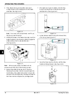
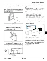
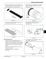
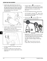
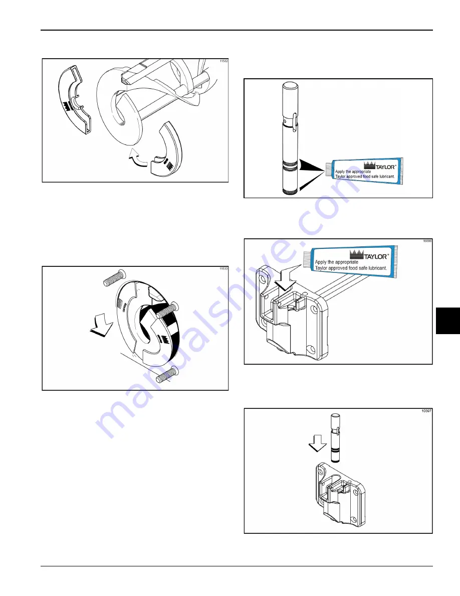
7. Install the beater shoes. (See Figure 6-18.)
Figure 6-18
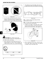
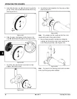
8. Slide the beater assembly the rest of the way into the
freezing cylinder. Make sure the beater assembly is
in position over the driveshaft by turning the beater
slightly until the beater is properly seated. When in
position, the beater will not protrude beyond the front
of the freezing cylinder. (See Figure 6-19.)
Figure 6-19
9. Before assembling the freezer door, check the
following for any nicks, cracks, or signs of wear: the
door bearing, door gasket, draw valve, O-rings, and
all sides of the door assembly, including the draw
valve bore. Replace any damaged parts.
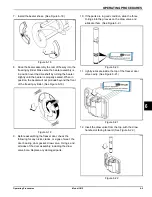
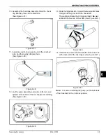
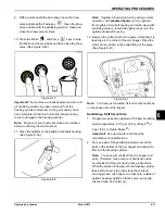
10. If the parts are in good condition, slide the three
O-rings into the grooves on the draw valve and
lubricate them. (See Figure 6-2.)
Figure 6-20
11. Lightly lubricate inside the top of the freezer door
valve cavity. (See Figure 6-21.)
Figure 6-21
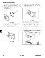
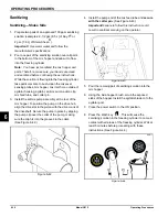
12. Insert the draw valve from the top, with the draw
handle slot facing forward. (See Figure 6-22.)
Figure 6-22
Summary of Contents for C612
Page 8: ...1 4 TO THE INSTALLER Model C612 To the Installer 1 Notes...
Page 54: ...9 2 PARTS REPLACEMENT SCHEDULE Model C612 Parts Replacement Schedule 9 Notes...
Page 58: ...10 4 LIMITED WARRANTY ON EQUIPMENT Model C612 Limited Warranty on Equipment 10 Notes...
Page 62: ...11 4 LIMITED WARRANTY ON PARTS Model C612 Limited Warranty on Parts 11 Notes...

