background image

1

Model 793

To the Installer

131206

Section 1

To the Installer

The following information has been included in the
manual as safety and regulatory guidelines. For
complete installation instructions, please see the
Installation Checklist.

Installer Safety

In all areas of the world, equipment should

be installed in accordance with existing local codes.
Please contact your local authorities if you have any
questions.

Care should be taken to ensure that all basic safety
practices are followed during the installation and
servicing activities related to the installation and
service of Taylor® equipment.

S

Only authorized Taylor service personnel
should perform installation, maintenance,
and repairs on Taylor equipment.

S

Authorized service personnel should consult
OSHA Standard 29CFRI910.147 or the
applicable code of the local area for the
industry standards on lockout/tagout
procedures before beginning any installation
or repairs.

S

Authorized service personnel must ensure
that the proper protective equipment (PPE)
is available and worn when required during
installation and service.

S

Authorized service personnel must remove
all metal jewelry, rings, and watches before
working on electrical equipment.

The main power supply(s) to the unit must

be disconnected prior to performing any installation,
maintenance, or repairs. Failure to follow this
instruction may result in personal injury or death
from electrical shock or hazardous moving parts as
well as poor performance or damage to the unit.

This unit has many sharp edges that can

cause severe injuries.

Site Preparation

Review the area where the unit will be installed.
Make sure that all possible hazards to the installer,
user, and the unit have been addressed.

For Indoor Use Only:

This unit is designed to

operate indoors, under normal ambient
temperatures of 70°-75°F (21°-24°C). The unit has
successfully performed in high ambient
temperatures of up to 104°F (40°C) at reduced
capacities.

This unit must

NOT

be installed in an area

where a water jet or hose can be used.

NEVER

use

a water jet or hose to rinse or clean the unit. Failure
to follow this instruction may result in electrocution.

This unit must be installed on a level surface

to avoid the hazard of tipping. Extreme care should
be taken in moving this unit for any reason. Two or
more persons are required to safely move this unit.
Failure to comply may result in personal injury or
damage to the unit.

The authorized installer should inspect the unit for
damage and promptly report any damage to the
local authorized Taylor distributor.

This unit is made using USA sizes of hardware. All
metric conversions are approximate and vary in size.

Air Cooled Units

DO NOT obstruct the unit's air intake and discharge
openings:

A minimum of 3” (76 mm) of air space is required on
all sides. Install the deflector provided to prevent
recirculation of warm air. Minimum air clearances
must be met to assure adequate air flow for
optimum performance.

Failure to allow adequate clearance can reduce the
refrigeration capacity of the unit and possibly cause
permanent damage to the compressor.

Summary of Contents for 793

Page 1: ...OPERATOR S MANUAL Model 793 Chick fil A Soft Serve Freezer Original Operating Instructions 082304CFAM 6 25 13 Original Publication Updated 12 6 13...

Page 2: ...Refrigeration Inc 082304CFAM Any unauthorized reproduction disclosure or distribution of copies by any person of any portion of this work may be a violation of Copyright Law of the United States of A...

Page 3: ...12 Air Tube 13 Section 6 Operating Procedures 14 Assembly 14 Sanitizing 18 Priming 20 Closing Procedure 20 Draining Product From The Freezing Cylinder 21 Rinsing 21 Cleaning 21 Disassembly 22 Brush C...

Page 4: ...inal set of instructions E 2013 Carrier Commercial Refrigeration Inc Original Publication Updated December 2013 082304CFAM Any unauthorized reproduction disclosure or distribution of copies by any per...

Page 5: ...rts as well as poor performance or damage to the unit This unit has many sharp edges that can cause severe injuries Site Preparation Review the area where the unit will be installed Make sure that all...

Page 6: ...authorities Each unit requires one power supply for each data label on the unit Check the data label s on the unit for branch circuit overcurrent protection or fuse circuit ampacity and other electri...

Page 7: ...r pressure is potentially hazardous and must be handled with caution NEVER fill any refrigerant cylinder completely with liquid Filling the cylinder to approximately 80 will allow for normal expansion...

Page 8: ...Warranty please see the Limited Warranty section in this manual If the crossed out wheeled bin symbol is affixed to this unit it signifies that this unit is compliant with the EU Directives as well as...

Page 9: ...anty Disclaimer section will not apply to the use of the alternate refrigerant approved by Taylor To find out the current status of an alternate refrigerant as it relates to your compressor warranty c...

Page 10: ...n or instruction concerning the use of the appliance by a person responsible for their safety is required Children should be supervised to ensure that they do not play with the appliance S All repairs...

Page 11: ...t in personal injury or damage to the unit Access to the service area of the unit must be restricted to persons having knowledge and practical experience with the unit in particular as far as safety a...

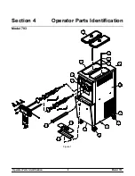
Page 12: ...8 Model 793 Operator Parts Identification Section 4 Operator Parts Identification Model 793 Figure 1...

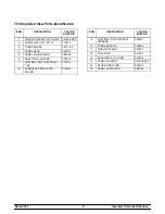
Page 13: ...5 4 PANEL REAR 041855 5 PANEL A SIDE RIGHT X82285 6 ADAPTOR A CASTER X18915 7 CASTER 4 SWV 5 8 STEM X 1 3 8 018794 8 SCREW 1 4 20X3 8 SLTD ROUND 011694 ITEM DESCRIPTION TAYLOR PART NO 9 CASTER 4 SWV 5...

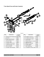
Page 14: ...RING 1 1 16 OD X 139W 020571 6 O RING 13 16 OD X 103W 019330 7 NUT STUD SHORT 034383 8 NUT STUD LONG 034382 9 HANDLE A DRAW NON ADJ X80916 ITEM DESCRIPTION TAYLOR PART NO 9a SCREW 5 16 24 X 625 06901...

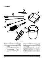
Page 15: ...REMOVAL 048260 2 BRUSH REAR BRG 1 OD X 2 X 14 013071 3 BRUSH DOUBLE ENDED 013072 4 BRUSH DRAW VALVE 1 OD X 2 X17 013073 ITEM DESCRIPTION TAYLOR PART NO 5 BRUSH MIX PUMP BODY 3 X 7 WHITE 023316 6 LUBRI...

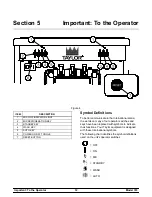
Page 16: ...ON OFF TOGGLE 7 RESET BUTTON Symbol Definitions To better communicate in the International arena the words on many of our operator switches and keys have been replaced with symbols to indicate their f...

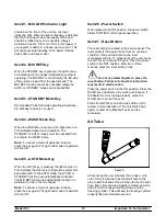
Page 17: ...e WASH or STANDBY functions are automatically cancelled The MIX REF function is automatically locked in to maintain the mix in the mix hopper Note To cancel a mode of operation function press the key...

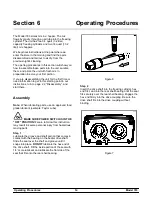
Page 18: ...ctions turn to page 22 Disassembly and start there Assembly Note When lubricating parts use an approved food grade lubricant example Taylor Lube MAKE SURE POWER SWITCH IS IN THE OFF POSITION Failure t...

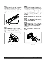
Page 19: ...r the remainder of the way into the freezing cylinder and over the end of the drive shaft The beater should fit snugly but not so tightly that the beater cannot be turned slightly to engage the drive...

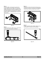
Page 20: ...he top Tighten equally in a crisscross pattern to ensure the door is snug Figure 11 Step 9 Install the draw valves Slide the two o rings into the grooves on the draw valves and lubricate Figure 12 Ste...

Page 21: ...insert them into the draw valves Secure with pivot pin Figure 15 Step 13 Snap the design cap over the end of the center door spout Figure 16 Step 14 Install the front drip tray and the splash shield u...

Page 22: ...of 100 200 PPM parts per million approved for use by your company Use warm water and follow the cleaning sanitizing solution manufacturer s specifications for dilution Step 2 Pour the sanitizing solu...

Page 23: ...Step 7 Place an empty pail beneath the door spouts Figure 25 Step 8 Open the center and side draw valve Draw off all the sanitizing solution Step 9 Once the sanitizer stops flowing from the door spout...

Page 24: ...ng When the unit cycles off the product will be at serving viscosity The MIX REF light will come on indicating the mix refrigeration system is operating to maintain the mix in the mix hopper Figure 27...

Page 25: ...rushes provided scrub the mix hopper mix inlet hole and mix level sensing probe Step 2 Place a pail beneath the door spouts and press the WASH key Step 3 Lower the center and side draw handles After t...

Page 26: ...ble draw handles S design caps S draw valves S all o rings Note To remove o rings use a single service towel to grasp the o ring Apply pressure in an upward direction until the o ring pops out of its...

Page 27: ...llowing day IMPORTANT The unit must be primed with FRESH mix Afterward during the day s operation rerun can be combined with fresh mix in a ratio of 50 50 Before using rerun skim off the foam and disc...

Page 28: ...our unit is water cooled check the water lines for kinks or leaks Kinks can occur when the unit is moved back and forth for cleaning or maintenance purposes Deteriorated or cracked water lines should...

Page 29: ...end e Contact authorized service technician to correct rotation to clockwise from operator end 2 The product is too stiff a The viscosity needs adjustment a Contact authorized service technician 3 The...

Page 30: ...eezer door a Install or replace the front bearing 15 b The beater assembly is bent b Call authorized service technician to repair or replace the beater and to correct the cause of insufficient mix in...

Page 31: ...equate level of mix in the mix hopper a Fill the mix hopper with mix 20 b The air tube is installed incorrectly b Make sure the end of the air tube with the small hole in the side is installed in the...

Page 32: ...t Seal X Scraper Blade X Freezer Door Gasket X Front Bearing X Draw Valve O Ring X Pivot Pin O Ring X Air Tube O Ring X White Bristle Brush 3 x 7 Inspect Replace if Necessary Minimum White Bristle Bru...

Page 33: ...ion compressor except service valve Five 5 years Beater motors Two 2 years Beater drive gear Two 2 years Printed circuit boards and Softech controls beginning with serial number H8024200 Two 2 years P...

Page 34: ...esulting from the use of any refrigerant other than that specified on the Product s data label will void this limited warranty 13 Any cost to replace refill or dispose of refrigerant including the cos...

Page 35: ...elve 12 months Class 512 Parts Twelve 12 months Class 000 Parts No warranty Taylor Part 072454 Motor 24VDC C832 C842 Four 4 years LIMITED WARRANTY CONDITIONS 1 If the date of original installation of...

Page 36: ...work promptly upon arrival 9 Failure damage or repairs due to faulty installation misapplication abuse no or improper servicing unauthorized alteration or improper operation or use as indicated in the...

Page 37: ...ST SALES LOST PROFITS PRODUCT LOSS PROPERTY DAMAGES OR SERVICE EXPENSES ARE EXPRESSLY EXCLUDED THE EXPRESS WARRANTIES MADE IN THIS LIMITED WARRANTY MAY NOT BE ALTERED ENLARGED OR CHANGED BY ANY DISTRI...

Page 38: ...75 4 000 BLOCK TERMINAL 3 P 039423 2 103 SCREW 8X1 1 4 PHLP HD RD B S 039420 4 000 BLOWER ASSEMBLY X53725 27 1 103 MOTOR BLOWER 053481 27 1 103 CAPACITOR RUN 7 5UF 370V 034749 1 103 BOOT CAPACITOR INS...

Page 39: ...0 BRUSH DOUBLE END 013072 1 000 BRUSH WHITE 1 X 2 013073 1 000 BRUSH WHITE 3 X 7 023316 1 000 BUSHING PANEL 013289 4 103 BUSHING PANEL 013289 2 103 BUSHING RUBBER MOUNT 012258 4 103 BUSHING SNAP 11 16...

Page 40: ...MIX HOPPER 041682 GRY 2 103 DECAL DEC TAYLOR 045812 CF 2 000 DECAL DOOR 3 SPOUT TWIN TWIST 021521 1 000 DECAL INST CLN HPR 019029 1 000 DECAL TROUBLESHOOT 038374 1 000 DEFLECTOR A EXHAUST X68702 1 103...

Page 41: ...15 250V 50 60 064173 1 1 000 GASKET FREEZER DOOR 048926 2 000 GEAR REDUCER 021286 SER 2 212 GUIDE A DRIP PAN X45691 1 103 HANDLE PULL 794 080701 1 103 BOLT EYE 1 4 20 X 3 4 ID 080702 2 000 NUT LOCK EL...

Page 42: ...NG 5 16 OD X 070W 016272 1 000 SEAL DRAW VALVE 034698 1 000 SEAL DRIVE SHAFT 032560 2 000 TOOL O RING REMOVAL FREEZER 048260 1 000 KIT MOUNTING COMPRESSOR 047704 1 000 LABEL ATTN SVC ENG 015068 2 000...

Page 43: ...103 NUT STUD LONG 034382 2 103 NUT STUD SHORT 034383 2 103 PAIL 013163 1 000 PAN DRIP 035034 1 103 PAN A HINGED DRIP X41844 1 103 PANEL A FRONT 794 X41820 SP2 1 103 PANEL A SIDE 794 LEFT X82284 1 103...

Page 44: ...E 022822 4 103 SHIELD SPLASH 022765 1 103 SHROUD CONDENSER REAR 068693 1 000 SHROUD CONDENSER FRONT 068694 1 000 SHROUD CONDENSER TOP 068695 1 000 STANDOFF COLLAR 066928 12 000 SCREW 10 32X1 1 4 SLTD...

Page 45: ...DRAW TWIN TWIST X39269 1 103 BRACKET SWITCH DRAW TWIN 039264 1 103 SCREW 4 40X1 2 HEX HEAD 3 16 042604 4 000 SWITCH LEVER SPDT 11A 125 27 039252 2 103 SWITCH A REED INTERLOCK DOOR X65658 1 103 SWITCH...

Page 46: ...8 230V 60HZ 3PH 3 WIRE W C BRISTOL R404A BLOWER 100 CFM 012796 27 1 103 GUARD BLOWER 022505 1 103 CONDENSER WC COAX 048287 2 103 FITTING A WATER OUTLET X69476 1 103 PIPE TEE 3 8 WATER VALVE 032953 1 1...

Page 47: ...Model 793 082065 33 Rev 6 13...

Reviews: