
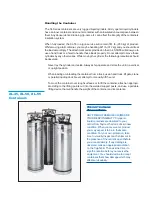
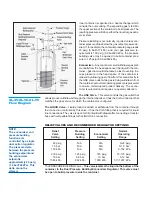


The XL-45 will store up to 169 liters of product, the XL-50 up to 181 liters and 200 liters
for the XL-55. All three cylinders can deliver either liquid or gas. The following compo-
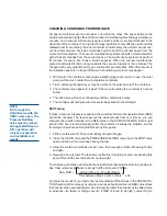
nent and circuit descriptions are pertinent to the operation of all the containers and
should be read before attempting operation. The components may be identified on the
Component Location Illustration.
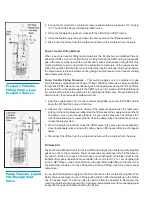
Internal Vaporizer –
A liquid container for gas service must have an internal heat ex-
changer that functions as a gas vaporizer coil to convert liquid product to gas continu-
ously during withdrawal. The XL-45/50/55 utilizes an internal heat exchanger that is inside
the vacuum space attached to the container’s outer casing. It provides a means of intro-
ducing heat from outside the container’s insulated jacket, to vaporize liquid as gaseous
product is withdrawn. The capacity of this circuit is sufficient to vaporize liquid as gaseous
product is withdrawn. The capacity of this circuit is sufficient to vaporize product at flow
rates up to 350 cfh @ NTP (9.2 cu. m/h @ STP). If a greater continuous demand is put on
the vaporizer, an external vaporizer should be added to properly warm the gas and avoid
malfunction, or damage, to gas regulators, hoses, and other downstream components.
Pressure Building –
A Pressure Building circuit is used to ensure sufficient driving pres-
sure during high withdrawal periods. This function is actuated by opening a hand valve that
creates a path from the liquid in the bottom of the container, through the Pressure Building
Regulator, to the gas space in the top. When the pressure building valve is open, and the
container pressure is below the pressure building regulator setting, liquid taken from the
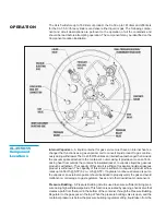
OPERATION
XL-45/50/55
Component
Locations