


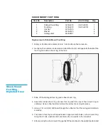

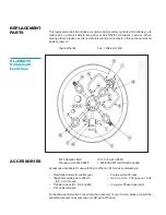

Index
Recommended
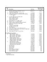
No.
Description
Part No.
For 10 Units
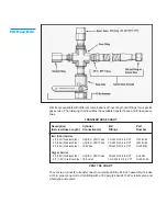
1.
Dual Regulator, Pressure Building/Economizer
69999-9015
2 Each
125 psig (8.6 bar/862 kPa)
* 2.
Gasket, Glass Filled Teflon, Contents Gauge
7701-0083
5 Each
3.
Contents Gauge Assembly (Includes Gauge and Spring)
GL45-9C65
1 Each
* Float Rod (45/50)
GL45-9C96
1 Each
(55)
GL45-9C97
1 Each
4.
Contents Gauge Cover, Protective Clear
GL50-9C54
4 Each
Snap-on indicator, Nitrogen
GL45-9C75
4 Each
Snap-on indicator, Oxygen
GL45-9C77
4 Each
Snap-on indicator, Argon
GL45-9C76
4 Each
5.
Screw, Brass, 1/4 in. - 20 UNC x 5/8 in.
6114-1088
10 Each
5a.
Washer, Lock, 1/4 in., Stainless Steel
6460-2025
10 Each
6.
Gauge, Pressure 0-400 psig (0-28 bar/0-2758 kPa)
7702-6196
2 Each
7.
Safety Head 380 psig (26 bar/2620 kPa)
1190-9C21
2 Each
8.
Relief Valve
**22 psig (1.5 bar/152 kPa)
6913-9069
5 Each
230 psig (16 bar/1586 kPa)
6913-9070
5 Each
9.
Valve Repair Kit
1750-9C35
3 Each
10.
Elbow, Male, Brass 45
°
3/8 in. ODT-comp x 1/4 in.
6814-9233
2 Each
11.
Connector, Lake, Brass, 3/8 in. ODT-comp x 1/4 in. NPT-EXT
4570-1960
2 Each
12.
Tube, P.B./Economizer Line
GL45-9C20
2 Each
14.
Elbow, Male, 3/8 in. NPT x 1/4 in. NPT 45
°
6814-9241
2 Each
End Fittings for Hand Valves
15.
-USE (CGA 540)-oxygen
7114-0163
5 Each
-USE (CGA 580)-argon/nitrogen
7114-0164
5 Each
-USE (CGA 320)-carbon dioxide
7114-0181
5 Each
-USE (CGA 326)-nitrous oxide
7114-0195
5 Each
16.
-LIQUID (CGA 440)-oxygen
6514-8992
5 Each
-LIQUID (CGA 295)-argon/nitrogen
7355-4712
5 Each
-LIQUID (CGA 320)-carbon dioxide
7114-0181
10 Each
-LIQUID (CGA 326)-nitrous oxide
7114-0195
10 Each
17.
-VENT (CGA 440)-oxygen
6514-8992
5 Each
-VENT (CGA 295)-argon/nitrogen
7355-4712
5 Each
-VENT (CGA 295)-carbon dioxide
7355-4712
5 Each
-VENT (CGA 295)-nitrous oxide
7355-4712
5 Each
*
Decal, Warning
1700-9C07
4 Each
*
Decal, Nitrogen
GL55-9C51
A/R
*
Decal, Oxygen
GL55-9C52
A/R
*
Decal, Argon
GL55-9C53
A/R
*
Decal, UN Number, Nitrogen
GL55-9C63
A/R
*
Decal, UN Number, Oxygen
GL55-9C64
A/R
*
Decal, UN Number, Argon
GL55-9C65
A/R
* Not illustrated.
** Optional/Not Illustrated.