Taylor-Wharton XL Series Instructions Manual Download Page 10

2. During the fill, monitor the container pressure and maintain a pressure of 10-15 psig

(0.7-1 bar/69-103 kPa) by throtting the VENT valve.

3. When the full weight is reached, close both the LIQUID and VENT valves.

4. Close the liquid supply valve and open the dump valve on the fill line assembly.

5. Disconnect the fill line from the container and remove the container from the scale.

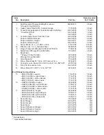
Pump Transfer Filling Method

When a pump is used for filling liquid containers, the fill may be accomplished through
either the VENT valve or the LIQUID valve. Filling through the VENT valve recondenses
gas in the area over the liquid in the cylinder and reduces product loss during the fill. This
method will also result in liquid near the saturation temperature of the supply vessel.
Filling through the LIQUID valve may provide colder liquid and longer holding time before
the liquid warms to the point where venting beings, but will require more frequent venting
and greater product loss.

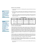
Pump Transfer Filling Procedure - 

 This method applies only to containers in gas

service that are equipped with a 230 psig (16 bar/ 1586 kPa) relief valve. Liquid is admitted
through the VENT valve and recondenses gas in the head space during the fill. The fill line
is connected from the liquid supply to the VENT valve on the cylinder. Both the fill line and
the container should be pre-cooled prior to beginning the fill process. Proper full weight is
determined by the previously explained method.

1. Open the supply valve. Then, on the container being filled, open only the VENT valve to

begin the fill. Start the pump at this time.

2. Observe the container pressure closely. If the pressure approaches the relief valve

setting (or the dump pressure rating) stop the fill process at the supply and open the fill
line dump valve to vent excess pressure. As soon as the pressure has dropped to a
level that will allow you to resume the fill, close the dump valve and restart the pump (or
reopen the supply valve.)

3. When full weight is reached, close the VENT valve. Stop pump (where applicable),

close liquid supply valve and open the dump valve on fill line assembly to vent trapped
liquid.

4. Disconnect the fill line from the container and remove the container from the scale.
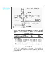
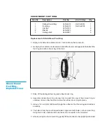
Fill Hose Kits

Taylor-Wharton fill hose kits for the XL-45/50/55 are designed to transfer specific liquefied
gases to, or from, the containers. These accessories are comprised of a Fill Tee Assem-
bly and a Fill Hose. Cryogenic transfer hoses are constructed of stainless steel for the
transfer of cryogenic liquids and are available in four or six feet (1.2 or 1.8 m) lengths with
a 3/8 in. NPT fitting on one end and CGA service-specific female fitting on the other. A Fill
Tee Assembly consists of a cross fitting with a CGA end fitting, relief valve and manual
dump valve.

In use, the CGA Tailpiece couples to the fill connection on the container being filled. The
Relief Valve vents pressure over 350 psig (24 bar/2413 kPa) that builds up in the fill line
due to trapped liquid. The Dump Valve is used to allow the operator to blow-down the
receiving container during a pump fill, or to relieve residual pressure from expanding liquid
trapped in the line before disconnecting the fill line.
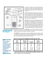
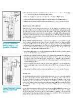
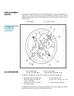
Pressure Transfer

Filling From a Low

Pressure Source

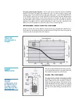
Pump Transfer Liquid

Fill Through Vent

Valve

Summary of Contents for XL Series

Page 1: ...and XL 55 with Dual Regulator Do not attempt to use or maintain this unit until you read and understand these instructions Do not permit untrained persons to use or maintain this unit If you do not f...

Page 2: ...nough oxygen for breathing will cause dizziness unconsciousness or even death These gases cannot be detected by the human senses and will be inhaled normally as if they were air Ensure there is adequa...

Page 3: ...kPa 16 bar 1586 kPa 16 bar 1586 kPa Inner Container Bursting Disc 380 psig 380 psig 380 psig 26 bar 2620 kPa 26 bar 2620 kPa 26 bar 2620 kPa Dual Pressure Building EconomizerRegulator PressureBuilding...

Page 4: ...When loading or unloading the container from a truck use a hand truck lift gate crane or parallel loading dock Never attempt to manually lift the unit q To move the container over rough surfaces or t...

Page 5: ...s insulated jacket to vaporize liquid as gaseous product is withdrawn The capacity of this circuit is sufficient to vaporize liquid as gaseous product is withdrawn The capacity of this circuit is suff...

Page 6: ...ls the gas outlet that allows product withdrawal through the internal vaporizer It has the CGA connection that matches the gas service for which the container is configured The LIQUID Valve Liquid pro...

Page 7: ...weight Relief Devices These cylinders have a gas service relief valve and inner container bursting disc with settings of 230 psig 16 bar 1586 kPa and 380 psig 26 bar 2620 kPa respectively A22 psig 1...

Page 8: ...ONTAINER Attach a transfer hose to the LIQUID connection and open the adjacent LIQUID valve The pressure in the container will drive liquid product out through the valve as long as the container press...

Page 9: ...55 higher pressure at the bulk vessel The pressure differential will then push the liquid from the storage vessel to the container being filled This method is employed when no transfer pump system is...

Page 10: ...egin the fill Start the pump at this time 2 Observe the container pressure closely If the pressure approaches the relief valve setting or the dump pressure rating stop the fill process at the supply a...

Page 11: ...295 to 3 8 in NPT 1700 9C65 6ft 1 8m StainlessSteel LIQUID or VENT Valve CGA 295 to 3 8 in NPT 1600 9C66 6ft 1 8m StainlessSteel USE Valve CGA 580 to 3 8 in NPT GL50 8C51 Oxygen Service 6ft 1 8m Stain...

Page 12: ...en and oxygen service for which the containers are designed Conver sion consists of changing the end connections at the USE LIQUID and VENT valves then changing the liquid level gauge scale by changin...

Page 13: ...of the regulator to raise or lower the pressure to the desired point When decreasing the setting the pressure building valve must be closed and the container vented to a lower pressure Then repeat ste...

Page 14: ...r and the dump valve Joints must be leak free before proceeding 2 Close the on off valve and the Dump valve 3 Slightly open the high pressure cylinder valve 4 Set the high pressure regulator above the...

Page 15: ...ld pressure for several days but will not hold liquid NER Testing If a loss of vacuum integrity is suspected the container s Normal Evaporation Rate NER should be checked The test measures the actual...

Page 16: ...ght tube 2 Support the gauge assembly by holding the base of the indicator tube Care must be taken to prevent interference with the spring action or from misaligning the scale sleeve Immerse teh alumi...

Page 17: ...careful during this portion of inser tion you will drop the float rod straight though the guide ring inside the cylinder 4 To confirm that the rod is correctly positioned in the cylinder stop where y...

Page 18: ...rque to about 20 ft lbf 2 8 kgf m Leak check the connection of gauge body to the flange CAUTION When installing the gauge assembly care must be taken to ensure that the float rod is inserted through t...

Page 19: ...14 Body TQ Torque 80 ft lbf 11 kgf m 1 Not available as a repair part Valve Disassembly Instructions 1 Open valve by turning handwheel counterclockwise as far as it will go to release any trapped gas...

Page 20: ...et 9 into valve body Hold body with one wrench and using another wrench 15 16 in socket tighten Bonnet to 80 ft lbf 11 kgf m torque 6 Install Bonnet Washers over Stem on Bonnet 7 Place Handwheel over...

Page 21: ...er shock ring to the tank 3 Slide off the damaged foot ring and rubber shock ring 4 Assemble rubber shock ring into new foot ring and force over shock mount ring on container Use a rubber hammer to dr...

Page 22: ...re source can be used to pressurize container No pressure shown 1 Bad container pressure 1 Remove and replace bad on container gauge gauge pressure gauge 2 Open inner container 2 Remove and replace bu...

Page 23: ...valve Economizer Regulator set regulator when in use above relief valve setting Economizer side of regulator clogged or stuck open Container vents after This may be caused by Symptom should go away f...

Page 24: ...3 8680 Theodore AL36590 0568 1 800 898 2657 in USA and Canada Accessories available for use with Taylor Wharton XL Series containers are Manifolds Automatic and Manual Container Hand Trucks Vaporizers...

Page 25: ...Each 10 Elbow Male Brass 45 3 8 in ODT comp x 1 4 in 6814 9233 2 Each 11 Connector Lake Brass 3 8 in ODT comp x 1 4 in NPT EXT 4570 1960 2 Each 12 Tube P B Economizer Line GL45 9C20 2 Each 14 Elbow M...

Reviews: