Electrical Troubleshooting
Section 4 Charger Troubleshooting
Page 7
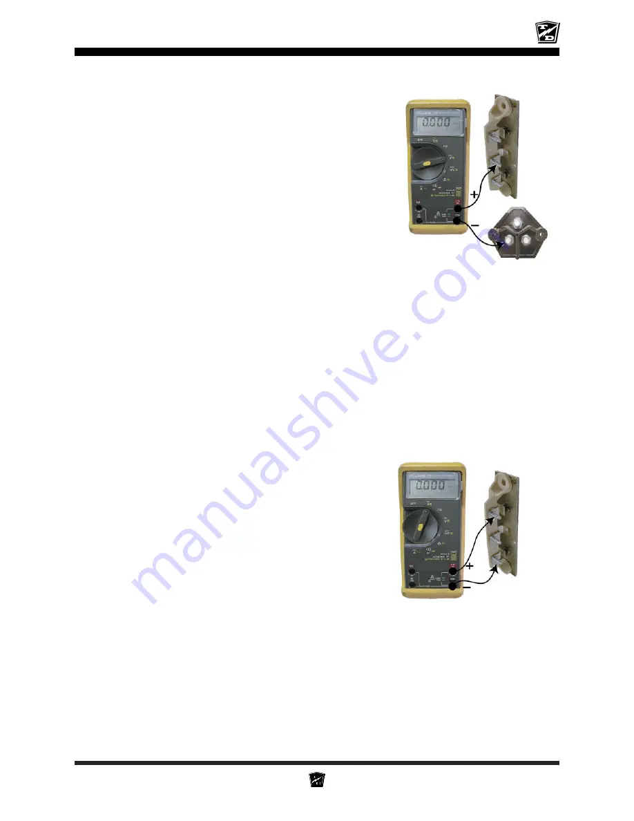
• Test the voltage from the fuse assembly (-) to the diode block (+).
This voltage should be equal to the battery voltage. If the voltage
is less than the battery voltage, then the wires from the harness
connectors to the charger are bad
. Stop here and repair the
problem.
• Test the voltage across the white and black wires that are connected to the timer board. This voltage
should be the same as the rated AC voltage of the charger. If the voltage is less than the rated AC
voltage of the charger, then the wires from the harness connectors to the charger are bad.
Stop here
and repair the problem.
• If the timer relay does not pickup (click) when the AC source is connected, then the timer control circuit
or the relay is bad (refer to Timer Relay Test).
Stop here and repair the problem.
• Test the AC voltage across the transformer primary circuit. The transformer primary consists of the two
solid wires with the brown fiber insulator that are connected to the timer board. This voltage should be
the same as the rated AC voltage of the charger. If the voltage is less than the rated AC voltage of the
charger, then the timer relay is bad.
Stop here and repair the problem.
• Test the AC voltage across the transformer low voltage secondary
circuit. The transformer low voltage secondary circuit can be
tested at the two solid wires with the brown fiber insulator that
are connected to the anodes on the two diodes. The voltage
here will vary depending on the state of charge in the batteries.
The voltage should be between 208% and 250% of the rated
DC voltage of the charger. If the voltage is not between 208%
and 250% of the rated DC voltage of the charger, the transformer
is bad and must be replaced.
Stop here and repair the
problem
.
Summary of Contents for SS5-34
Page 2: ......
Page 13: ...Vehicle Description and Specifications Describes the Vehicle and Its Standard Specifications...
Page 31: ...3 7 NOTES...
Page 43: ...3 19 Exploded view of mechanical rear brake assembly...
Page 78: ...TAYLOR DUNN...
Page 79: ...SECTION 4 Electrical Troubleshooting...
Page 101: ...Vehicle Wire Diagrams Section 4A...
Page 133: ...Illustrated Parts List...
Page 135: ...5 3 SS5 34 SS5 36 MX 600 SS5 46...
Page 136: ...5 4 ILLUSTRATED PARTS BRAKE PEDALLINKAGE AND ACCELERATOR PEDAL SS5 34...
Page 140: ...5 8 ILLUSTRATED PARTS FRONTAXLE WHEELAND SUSPENSION SS5 34 SS5 36 MX 600...
Page 144: ...5 12 ILLUSTRATED PARTS TILLER STEERING...
Page 146: ...5 14 ILLUSTRATED PARTS GEARED STEERING SS5 34...
Page 148: ...5 16 ILLUSTRATED PARTS GEARED STEERING SS5 36 SS5 46 AND MX 600...
Page 150: ...5 18 ILLUSTRATED PARTS INSTRUMENT PANEL SS5 34 SS5 36 AND SS5 46...
Page 152: ...5 20 ILLUSTRATED PARTS CONTROLS AND INSTRUMENTS MX 600...
Page 156: ...5 24 ILLUSTRATED PARTS MOTOR SS5 36 SS5 46 MX 600 2 3 5 6 4 7 8 1 9 10 Armature 12...
Page 158: ...5 26 ILLUSTRATED PARTS REAR AXLE SS5 34 1 2 3 4 5 6 8 11 12 10 9 13 7...
Page 160: ...5 28 ILLUSTRATED PARTS REAR AXLE SS5 36 SS5 46 AND MX 600...
Page 162: ...5 30 ILLUSTRATED PARTS DIFFERENTIAL SS5 34...
Page 164: ...5 32 ILLUSTRATED PARTS DIFFERENTIAL SS5 36 SS5 46 AND MX 600...
Page 166: ...5 34 ILLUSTRATED PARTS SS5 36 SS5 46 DIFFERENTIAL FRAME...
Page 168: ...5 36 ILLUSTRATED PARTS DECK AND VISEASSY MX 600...
Page 170: ...5 38 ILLUSTRATED PARTS TOOLBOX ASSY MX 600 1 2 3 4 5 6...
Page 174: ...5 42 ILLUSTRATED PARTS BRAKE ASSY SS5 34...
Page 176: ...5 44 ILLUSTRATED PARTS REAR BRAKE SS5 36 SS5 46 AND MX 600...
Page 178: ...5 46 ILLUSTRATED PARTS PMC CONTROL PANEL...
Page 182: ...5 50 ILLUSTRATED PARTS TIRE AND WHEEL...
Page 184: ...5 52 ILLUSTRATED PARTS SEAT CUSHIONS SS5 34 SS5 36 SS 5 46 MX 600...
Page 186: ...5 54 ILLUSTRATED PARTS DECALS...
Page 188: ...5 56 ILLUSTRATED PARTS MIRRORS OPTION...
Page 190: ...5 58 ILLUSTRATED PARTS STROBE AND STOP LIGHT OPTION...
Page 194: ...TAYLOR DUNN...
Page 195: ...Parts Appendix A...
Page 198: ...TAYLOR DUNN...
Page 199: ......


