98
Opening
To open the ISM main circuits, a trip command should be applied to the CM trip command input. It is a “dry
contact“ input so no external voltage should be applied. The trip command will be accepted if:
CM state is “Ready” (Ready LED flashes green) or within 60 seconds after the removal of the auxiliary
power supply;
optional electrical interlock is unlocked;
mechanical and electrical interlock is unlocked (in case of ISM15_MD_1, ISM15_MD_3, ISM15_Shell_2
and ISM15_HD_1 only)
If the trip command is applied and kept before the CM is in a “Ready“ state, the
trip command will not be accepted.
Emergency opening
The ISM can also be opened manually. When the synchronizing shaft is rotated, a force exceeding the
magnetic attraction forces of the ring magnet is applied to the armature, which subsequently starts to move.
As the air gap increases, the opening springs and the contact pressure springs overcome the magnetic holding
force, and the vacuum interrupter opens.
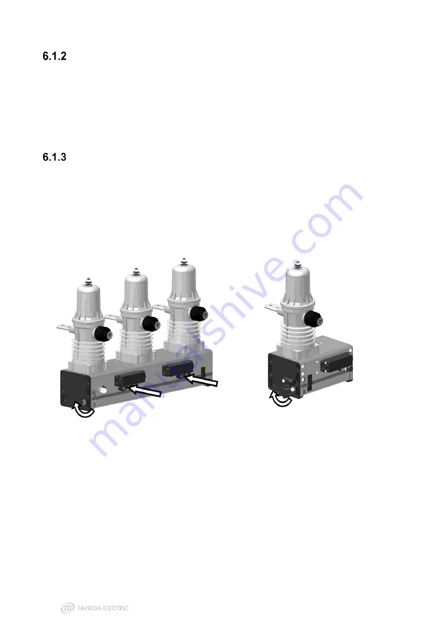
To open the ISM15_LD_1, LD_3, LD_6 and ISM25_LD1, LD_2, LD_3 manually, the force shall be applied to
the interlocking pins or torque shall be applied to the stub shaft evenly during their movement - see Figure
158
. Force shall be applied along the pin‘s movement axis and directed to the ISM frame. The torque shall be
applied in the direction of shaft rotation during ISM opening. The force or torque influence shall not be applied
at the end of pin‘s stroke or shaft rotation and shall not be applied to the pin or shaft before ISM closing.
Figure 158
ISM15_LD_1, LD_3, LD_6 and ISM25_LD1, LD_2, LD_3 manual trip execution.
Force or torque can be applied to any of the points shown above
To open the ISM15_LD_8, ISM15_MD_1, ISM15_MD_3, ISM15_Shell_2 and ISM15_HD_1 manually, the
torque shall be applied to the interlocking shaft evenly during its movement - see Figure 159. The torque shall
be applied counterclockwise of shaft rotation (90 degrees angle). The torque shall not be applied at the end of
shaft rotation. ISM15_LD_8, ISM15_MD_1, ISM15_MD_3, ISM15_Shell_2 and ISM15_HD_1 have a built in
electrical interlock that interrupts the ISM coil circuit after the interlocking shaft is rotated counterclockwise.
After manual trip, the shaft should be rotated clockwise to unlock the ISM.
Summary of Contents for VCB Series
Page 1: ...COMPATIBLE SERIES USER GUIDE...
Page 2: ......
Page 4: ......
Page 5: ...1 Product description...
Page 13: ...13 2 Nameplates and seals...
Page 18: ...18 3 Product handling...
Page 37: ...4 Installation...
Page 87: ......
Page 88: ...5 Commissioning...
Page 94: ...94 Figure 155 The connection points of the contact resistance meter...
Page 95: ......
Page 96: ...6 Operation...
Page 100: ...7 Maintenance and troubleshooting...
Page 105: ......
Page 106: ...8 Disposal...
Page 109: ...109 Appendix 2 Overall Drawings...
Page 112: ...112 ISM15_LD_3 Weight 13 kg ISM15_LD_6 PCD 133 mm Weight 55 kg...
Page 113: ...113 ISM15_LD_8 PCD 210 mm Weight 26 kg...
Page 114: ...114 ISM15_MD_1 150_L PCD 150 mm Weight 33 kg ISM15_MD_1 210_L PCD 210 mm Weight 35 kg...
Page 115: ...115 ISM15_MD_3 Weight 13 kg ISM15_Shell_2 150_L PCD 150 mm Weight 51 kg...
Page 120: ...120 ISM15_HD_1 275 PCD 275 mm Weight 72 kg ISM25_LD_1 210_Par2 PCD 210 mm Weight 36 kg...
Page 123: ...123 ISM25_LD_2 2 PCD 150 mm Weight 37 kg ISM25_LD_3 Weight 14 kg...
Page 125: ...125 Dimensions of Control Module CM_16_1 Par1_Par2_Par3_Par4_Par5 Weight 1 kg...
Page 127: ...127 Dimensions of Interlocking Kits CBkit_Interlock_1 CBkit_Interlock_3...
Page 128: ...128 CBkit_Interlock_4 CBkit_Interlock_5...
Page 129: ...Appendix 3 Secondary Schemes...
Page 130: ...130...
Page 131: ...131...
Page 132: ...132...
Page 133: ...133...
Page 134: ...134...
Page 135: ...135...
Page 136: ...136...
Page 137: ...137...
Page 138: ...138...
Page 139: ...139...
Page 140: ...140...
Page 142: ...Bartlett...


