background image

ISM Shell_2 Series

Vacuum Circuit Breaker
15kV, ...29kA, ...2000A

Applications Manual MAN5002239 
Revision 4

Summary of Contents for ISM Shell_2 Series

Page 1: ...ISM Shell_2 Series Vacuum Circuit Breaker 15kV 29kA 2000A Applications Manual MAN5002239 Revision 4...

Page 2: ...2...

Page 3: ...rts also remote controlled can move quickly Failure to comply may result in death severe personal injury or damage to equipment Pay attention to the hazard statements located throughout this manual Th...

Page 4: ...ion Indicator 26 Secondary Connections of the ISM 29 CM connections 30 CM_16 Series Factory Programmable Options 32 Ins tallation of the CM 34 Ins tallation of Secondary Cables between ISM and CM 35 4...

Page 5: ...s CM16 Series 54 9 Dimens ions and Weights Dimens ions and Weights of the ISM 56 Dimens ions and Weights of the CM 59 Dimens ions of the Position Indicator 60 Dimens ions of Mating Part for Interlocki...

Page 6: ...6 1 THIS PAGE INTENTIONALLY LEFT BLANK...

Page 7: ...7 Introduction 1...

Page 8: ...result in death or serious injury CAUTION Indicates a potentially hazardous situation that if not avoided could result in personal injury or equipment damage Safety Instructions General hazard stateme...

Page 9: ...is the time period from the energising of the closing circuit up to the time when the arcs of all the poles are extinguished Open close time during AR Interval of time between the instant when the ar...

Page 10: ...ents the Tavrida Electric circuit breaker monitors its status continuously In the unlikely event that a fault occurs it is indicated and can be rectified before an unsuc cessful switching attempt is m...

Page 11: ...t may be opened manually by means of interlocking shaft rotating counter clockwise The interlocking cam of interlocking shaft act on the armature when then starts to move refer to chapter Installation...

Page 12: ...12 1 THIS PAGE INTENTIONALLY LEFT BLANK...

Page 13: ...13 Receiving Handling and Storage 2...

Page 14: ...ht on the delivery unit 5 Serial number 5 A label with the following information is fixed on each CM carton package Figure 10 1 2 3 4 5 6 1 Manufacturer 2 Product name 3 Type of device 4 Serial number...

Page 15: ...e unpacking please check the carton for damage and dampness Removal of the products from the original packing must be carried out with due care Every ISM and every CM shall be subject to a completenes...

Page 16: ...espond to the data of the order The rating plate for the ISM contains the following information Figure 13 1 Manufacturer 2 Type of device 3 Rated maximum voltage 4 Rated impulse withstand voltage 5 Ra...

Page 17: ...tified to CAN CSA 22 2 No 142 M1987 Tavrida Electric North America 1105 Cliveden Ave Delta BC Canada 1 866 551 8362 Made in Russia 4000068 1 2 3 4 5 4 6 7 8 9 1 Model type 2 Auxiliary power supply min...

Page 18: ...ants must be placed in the packing Storage must be dry well ventilated and the room temperature should be between 40 C and 40 C IEC694 DIN VDE 0670 Part 1000 If several ISM are stacked a maximum of tw...

Page 19: ...19 Ins tallation 3...

Page 20: ...with a rough dry cloth With hard oxidation clean with a hard plastic sponge the upper layer must not be removed For ISM fixing and terminal connections steel bolts according to EN ISO 898 class 8 8 8...

Page 21: ...f connection ISM terminal with contact arm using the mounting assembly Figure 20 Figure 21 Primary terminals connection Bus bars and cables shall be connected with the primary terminals of ISM mechani...

Page 22: ...ype tubes are bracketed Figure 24 Minimum distances between parts of switching module and grounded metal enclosure of switchboard Figure 25 Ur Up Minimum clearance L2 15 kV 95 kV 120 mm Module Short c...

Page 23: ...able regulations such as DIN VDE 0141 DIN VDE 0151 IEC 6021 2 via the marked two ground screws of the ISM to the ground arrangement of the particular panel One or both grounding bolts can be used If t...

Page 24: ...rotation of the interlocking shaft from unlatched to open and locked position leads to the manual tripping of the module and afterwards to the mechanical blocking of the actuator Working principle of...

Page 25: ...nded This handle shall be freely rotated up to 90 degrees in both directions The handle operated by fingers shall be dimensioned so as to provide rotating force in accordance with local standards Poss...

Page 26: ...age 38 If the mechanical interlocking is effective then the electrical interlocking contact is activated synchronously Electrical interlocking occurs during first 10 degree of interlocking shaft rotat...

Page 27: ...mechanism 1 2 3 4 5 Indication of ISM position by indicator plate depending on position of synchronizing shaft trunnion Figure 37 Position indicator with flexible link Figure 38 Position of trunnion a...

Page 28: ...tor Figure 40 Unscrew the self tapping screws of transparent cover Remove the cover Figure 41 Drop the boss of the wire horizontally into slot Insert end of the sheath into V shape spring contact So t...

Page 29: ...itch S 1 4 16 Auxiliary switch S 13 AS2 3 Auxiliary switch S 2 1 17 Auxiliary switch S 7 1 4 Auxiliary switch S 2 4 18 Auxiliary switch S 7 2 5 Auxiliary switch S 3 1 19 Auxiliary switch S 8 1 6 Auxil...

Page 30: ...put actuator coil SC2 5 Dry contact Close 6 Dry contact Trip 7 Dry contact Trip 8 Malfunction NO 9 Malfunction COM 10 Malfunction NC Figure 47 CM_1501_01 Terminal arrangement Power supply voltage can...

Page 31: ...input 2 4 Digital output 1 COM 4 CT input 2 5 Digital output 1 NC 6 Digital output 2 NO 7 Digital output 2 COM 8 Digital output 2 NC 9 Digital output 3 NO 10 Digital output 3 COM 11 Digital output 3...

Page 32: ...ts signal a loss of auxiliary supply signal ready for operation or signal a malfunction Trip Close Delays The ISM breaker series have high speed actuators for trip and close operations The CM_16 by de...

Page 33: ...40 Close Delay Close delay 4 40 ms 4 40 Trip Input By closing the contact 1 By opening the contact 2 Close Input By closing the contact 1 By opening the contact 2 Example For a control module program...

Page 34: ...anel design either on the draw out unit or in the low voltage compartment of the switchboard It must be separated from the high voltage compartment The CM shall be installed in an grounded mild steel...

Page 35: ...nce Unshielded parts of wires to ground point and to CM not more than 10 cm Grounding point as near as possible at CM 2 1 3 3 3 3 4 5 6 7 Actuator coil 3 3 ISM position switch Grounding points are ava...

Page 36: ...36 3 THIS PAGE INTENTIONALLY LEFT BLANK...

Page 37: ...37 Switching and Control Functions 4...

Page 38: ...e type of malfunction see the Signalling chapter of this manual At the same time the Malfunction relay output contact will close In this way a CM Malfunction state can be transmitted to an alarm or SC...

Page 39: ...tuator are monitored permanently see malfunction indication table page 43 Internally at the auxiliary switch inputs of the CM_1501 230 V DC is applied for the ISM auxiliary switch S13 The CM_16 series...

Page 40: ...tipumpingDuty A close command during a pending trip command is not executed blocking duty even it is pending longer than the trip command antipumping duty Figure 56 Close contact Trip contact Output t...

Page 41: ...41 Commiss ioning Maintenance 5...

Page 42: ...fit is carried out on energized equipment the relevant safety regulations for local and national standards must be adhered to When designing and mounting a panel for the first time an acceptance of th...

Page 43: ...D is extinguished the voltage has dropped to a safe value In the factory the magnetic actuator coils are connected and tested according to the existing circuit diagram If the actuator coil is connecte...

Page 44: ...44 5 THIS PAGE INTENTIONALLY LEFT BLANK...

Page 45: ...45 Signalling 6...

Page 46: ...d relay configuration The relays will change state from unasserted to asserted based on the firmware logic as outlined in the chart below Note that as the relays are latching types they will retain th...

Page 47: ...on the ISM can be switched off again by the CM This deletes the malfunction indication although the malfunction still exists Check for short circuit in the cable Check for short circuited terminals Ch...

Page 48: ...operly closed by the CM and the close position feedback exists Then a malfunction occurres in the ISM auxiliary switch S13 circuit in which the normally open switch S13 is bridged the ISM can still be...

Page 49: ...49 Special Applications Fast Switching 6...

Page 50: ...es 1 Closed transition the backup power line is connected by closing the breaker before the main line is interrupted make before break 2 Open transition the backup power line is connect by closing the...

Page 51: ...rc is suppressed the lower the energy output and therefore less damage to equipment plus improved operator safety Tavrida ISM_Shell_2 series breakers unique high speed opening characteristics allow fo...

Page 52: ...hanical life 4 CO cycles 30 000 Operating cycles 4 rated current CO cycles 30 000 Operating cycles 4 rated short circuit breaking current O operations 50 Closing time 3 22 ms Opening time 3 not more t...

Page 53: ...53 Product Line 7...

Page 54: ...es can be factory set for fast operation 4 11 ms acceptance time Type Former Product Code Rated Voltage General Functionality CM_1501_01 12 N A 100 270 VAC VDC Basic functionality 12 ms trip delay tim...

Page 55: ...55 Dimens ions and Weights 8...

Page 56: ...05 Cliveden Ave Delta BC V3M 6G9 Canada Tel 604 540 6600 Fax 604 540 6604 www tavrida na com Three phase indoor switching module with 95 kV BIL and 1200 A of rated current Assembly drawing CUSTOMER PR...

Page 57: ...6604 www tavrida na com Three phase indoor switching module with 95 kV BIL and 2000 A of rated current Assembly drawing CUSTOMER PROJECT TITLE 1 2 5 A Belozub DWG FV ALL_ISM15_Shell_2 210 AD APPROVED...

Page 58: ...4 x 2 Nameplate FV ALL_Pack_Nameplate_2 7 1 2 Switching module FS SM_ISM15_Shell_2 275_H 1 1 REFERENCE DESCRIPTION PART NUMBER QTY ITEM 1 1 2 2 3 3 4 4 5 5 6 6 7 7 8 8 SHEET 1 OF 1 DRAWN CHECKED P Vo...

Page 59: ...Dimens ions and Weights of the CM CM_1501_01 Weight 1 5 kg CM_1501_01 12 CM_1501_01 4 CM_16_1 Weight 1 5 kg CM_16_1 60 CM_16_1 220 CM_16_1 60HS CM_16_1 220HS CM_16_2 Weight 1 5 kg CM_16_2 220 CM_16_2...

Page 60: ...60 Dimens ions of the Position Indicator L 1 m Dimens ions of Mating Part for Interlocking Shaft Dimensions of interlocking shaft 8...

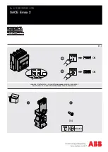
Page 61: ...61 8 Mating part with interlocking lever Interlockingshaftwithmountedinterlockinglever...

Page 62: ...62 Circuit Diagrams 9...

Page 63: ...63 ISM15_Shell_2 with CM_1501_01 9...

Page 64: ...64 ISM15_Shell_2 with CM_16_1 9...

Page 65: ...65 9 THIS PAGE INTENTIONALLY LEFT BLANK...

Page 66: ...66 Technical Data 10...

Page 67: ...ccordancewithIEC60932 Class 1 Standards IEC 62271 100 GB 1984 2003 ANS C37 09 Mechanical vibration withstand capability according to IEC 60271 IEC 60068 Class 4M4 Other data Resistance of main circuit...

Page 68: ...andby 5 W 8 VA 5 W 7 W Reaction times Preparation time for the operation of the CM after switching on the auxiliary power supply not more than 15 s 15s 15s Preparation time for the close operation of...

Page 69: ...V A 100 A m for duration of 60 s 1000 A m for duration of 2 s Interference immunity to pulsed magnetic fields to IEC 61 000 4 9 Class V A 1000 A m Interference immunity to damped oscillations of the...

Page 70: ...16_2 Input for CT power supply Operating current range 2 300 A Power consumption per phase during charging trip capacitors at 2 A 5 VA at 5 A 12 VA at 10 A 25 VA at 30 A 120 VA at 300 A 8 kVA Preparat...

Page 71: ...71 10 THIS PAGE INTENTIONALLY LEFT BLANK...

Page 72: ...72 Regulations and Ambient Conditions 11...

Page 73: ...insulation measurement of the ISM must be increased by the atmospheric correction factor Ka according to IEC 62271 1 compared to the insulation measurement at sea level Figure 59 Example Installation...

Page 74: ...74 Legal Information 12...

Page 75: ...d in an electronic database for each step of the manufactu ring process Testing of the circuit breakers is carried out inaccordancewiththerelevantstandardsandbeyondthat the following test are carried...

Page 76: ...e body or health A change of the obligation to provide proof to the disadvantage of the customer is not connected with these regulations Copyright Without our written permission this documentation may...

Page 77: ...77 12 THIS PAGE INTENTIONALLY LEFT BLANK...

Page 78: ...ions of ISM comply with technical data specified in Technical Manual Unsupported busbar length page 21 Fixing points page 21 Bolts and torques pages 20 21 23 Minimum clearances due to rated insulation...

Page 79: ...79 Date 12...

Page 80: ...80 Date 12...

Page 81: ...81 Date 12...

Page 82: ...82 THIS PAGE INTENTIONALLY LEFT BLANK...

Page 83: ...ny form without written permission fromTavrida Electric Tavrida Electric applies a policy of ongoing development and reserves the right to change product without notice Tavrida Electric does not accep...

Reviews: