ComAp InteliMains NT IM-NT, Reference Manual
The ComAp InteliMains NT IM-NT Reference Manual is essential for understanding and operating this innovative product. You can download the manual for free from manualshive.com, providing you with clear instructions and insights on how to optimize the performance of your InteliMains NT IM-NT system.
Share
Download


Reviews:
No comments
Related manuals for InteliMains NT IM-NT

T6N
Brand: CAME Pages: 112

PKZM0-0,16
Brand: Eaton Pages: 76

FP 61
Brand: Areva Pages: 41

OFI-125
Brand: OEZ Pages: 6

SV 9677.100
Brand: Rittal Pages: 20

SV 9677.000
Brand: Rittal Pages: 20

Porcel-line 150 DHP 1000
Brand: Westinghouse Pages: 78

Btdin B6338D
Brand: Bticino Pages: 5

FAZ-XAA Series
Brand: Eaton Pages: 2

xComfort CSEZ-01/16
Brand: Eaton Pages: 2
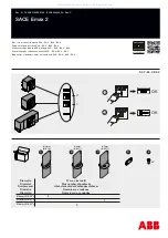
SACE Emax 2 E2.2
Brand: ABB Pages: 6

IZM Series
Brand: Eaton Pages: 12

SACE Emax
Brand: ABB Pages: 15

MCB Series
Brand: Circutor Pages: 2

RECmax Lpd
Brand: Circutor Pages: 40

RECmax-CVM 2-pole
Brand: Circutor Pages: 68

EB1v1
Brand: NCE Pages: 6


