Hardware Description
15
The USART supports the connection to the Peripheral DMA Controller, which enables
data transfers to the transmitter and from the receiver. The PDC provides chained buffer
management without any intervention of the processor.
Six different modes are implemented within the USARTs:
• Normal (standard RS232 mode)
• RS485
• Hardware Handshaking
• ISO7816 Protocol: T=0 or T=1
• IrDA
RS485.
In RS485 operating mode the RTS pin is automatically driven high during
transmit operations. If RTS is connected to the "enable" line of the RS485 driver, the driver
will thus be enabled only during transmit operations.
Hardware Handshaking.
The hardware handshaking feature enables an out-of-band
flow control by automatic management of the pins RTS and CTS. The receive DMA channel
must be active for this mode. The RTS signal is driven high if the receiver is disabled or if
the DMA indicates a buffer full condition. As the RTS signal is connected to the CTS line of
the connected device, its transmitter is thus prevented from sending any more characters.
ISO7816.
The USARTs have an ISO7816-compatible mode which permits interfacing
with smart cards and Security Access Modules (SAM). Both T=0 and T=1 protocols of the
ISO7816 specification are supported.
IrDA.
The USART features an infrared (IrDA) mode supplying half-duplex point-to-
point wireless communication. It includes the modulator and demodulator which allows
a glueless connection to the infrared transceivers. The modulator and demodulator are
compliant with the IrDA specification version 1.1 and support data transfer speeds ranging
from 2.4 kb/s to 115.2 kb/s.
Signals of the Serial Interfaces.
All UARTs/USARTs have one receiver and one
transmitter data line (full duplex). Not all USARTs are implemented with full modem
control lines. Furthermore the available lines depend largely on the used multiplexing.
Most modem control lines can be implemented with standard digital ports.
Hardware Interrupts.
There are several interrupt sources for each USART:
• Receive: RX Ready, (DMA) Buffer Full, End of Receive Buffer
• Transmit: TX Ready, (DMA) Buffer Empty, End of Transmit Buffer, Shift Register Empty
• Errors: overrun, parity, framing, and timeout errors
• Handshake: the status of CTS has changed
• Break: the receiver has detected a break condition on RXD
• NACK: non acknowledge (ISO7816 mode only)
Summary of Contents for Panel-Card
Page 1: ...Panel Card Technical Reference ...
Page 32: ...Panel Card Starterkit 26 Figure 6 1 Panel Card EVB Schematics Bus JTAG ...
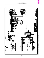
Page 33: ...Panel Card Starterkit 27 Figure 6 2 Panel Card EVB Schematics USB RS232 ...
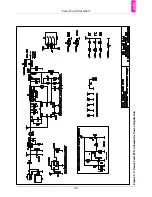
Page 34: ...Panel Card Starterkit 28 Figure 6 3 Panel Card EVB Schematics Power Regulation ...
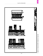
Page 35: ...Panel Card Starterkit 29 Figure 6 4 Panel Card EVB Schematics Connectors ...
Page 36: ...Panel Card Starterkit 30 Figure 6 5 Panel Card EVB Schematics HID ...
Page 39: ...Panel Card Starterkit 33 Figure 6 8 Panel Card Connector Schematics USB Ethernet ...
Page 49: ...Panel Card Dimensions 43 Appendix H Panel Card Dimensions Figure H 1 Panel Card 35 Dimensions ...
Page 50: ...Panel Card Dimensions 44 Figure H 2 Panel Card 57 Dimensions ...

