Hardware Description
19
Blue[7..0]
Green[7..0]
Red[7..0]
Table 4.5. LCDC 24 bit memory organization
The "BGR" (blue-green-red) sequence in the AT91SAM9261 LCDC is not frequently used
by graphics libraries or bitmaps ("RGB" is more of a standard), neither is the use of bit
15 as an intensity bit. Of course, the first problem can be circumvented by connecting
the LCDC lines to the LCD in a way deviating from the Atmel designation, that is, by
exchanging the "blue" against the "red" lines.
The Linux frame buffer driver offers a function which returns the information about the
frame buffer structure including the assignment of each frame buffer bit to a color channel
bit. It is recommended that graphics software uses this function in order to achieve a
correct color representation.
4.26. Display (TFT)
Panel-Cards with the following displays are available:
• ET035005DM6 (3,5″, 320x240, BGR)
• ET057011DHU (5,7″, 320x240, RGB)
• ET057009DHU (5,7″, 640x480, RGB)
All TFTs have a LED backlight which can be dimmed and switched off. Panel-Cards with
ET035005DM6 use PIO ports PC4 and PC5 to dim the backlight and it is switched off
with PC1. PC10 is used to switch off the TFT power supply. On the other Panel-Cards, the
backlight is dimmed by the contrast value of the LCDC. Both the backlight and the TFT
power supply is switch off with PC10.
4.27. Touchscreen
The Panel-Card 35 is available with a touch. However, it does not have a touch controller
on board, so it has to be implemented on the base board. A reference implementation with
an ADS7843 touch controller can be found on the Panel-Card Evaluation board.
Panel-Card 57/70 always have a touchscreen and use the ADS7846 touch controller.
4.28. Ethernet Controller
The product is equipped with a Davicom DM9000A 10/100 MBit Ethernet Controller and
a 10/100 MBit Twisted-Pair Magnetic Module (transformer plus filter).
An individual 48-bit MAC address (ETHERNET hardware address) is allocated to each
product. This number is stored in flash memory. It is recommended not to change the MAC
address in order to comply with IEEE Ethernet standards.
4.29. Buttons
The Panel-Card 57/70 have five buttons connected to PIO pins PA17-PA21.
Summary of Contents for Panel-Card
Page 1: ...Panel Card Technical Reference ...
Page 32: ...Panel Card Starterkit 26 Figure 6 1 Panel Card EVB Schematics Bus JTAG ...
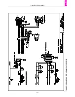
Page 33: ...Panel Card Starterkit 27 Figure 6 2 Panel Card EVB Schematics USB RS232 ...
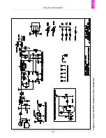
Page 34: ...Panel Card Starterkit 28 Figure 6 3 Panel Card EVB Schematics Power Regulation ...
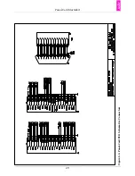
Page 35: ...Panel Card Starterkit 29 Figure 6 4 Panel Card EVB Schematics Connectors ...
Page 36: ...Panel Card Starterkit 30 Figure 6 5 Panel Card EVB Schematics HID ...
Page 39: ...Panel Card Starterkit 33 Figure 6 8 Panel Card Connector Schematics USB Ethernet ...
Page 49: ...Panel Card Dimensions 43 Appendix H Panel Card Dimensions Figure H 1 Panel Card 35 Dimensions ...
Page 50: ...Panel Card Dimensions 44 Figure H 2 Panel Card 57 Dimensions ...


