Address Map (Physical Address Space)
37
Appendix C. Address Map (Physical
Address Space)
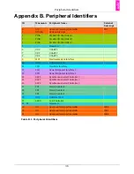
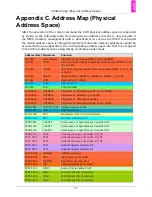
After the execution of the remap command the 4 GB physical address space is separated
as shown in the following table. Accessing these addresses directly is only possible if
the MMU (memory management unit) is deactivated. As soon as the MMU is activated
the visible address space is changed completely. If absolute memory addresses should be
accessed within an application, the corresponding address space has first to be mapped
to the virtual address space using mmap or ioremap under Linux.
Address (Hex) Mnemonic
Function
00 0000
Boot Memory
Flash (NCS0) or internal ROM or internal SRAM
10 0000
ITCM
Instruction TCM (Tightly Coupled Memory) Internal SRAM A: 0, 16,
32 or 64 kB
20 0000
DTCM
Data TCM (Tightly Coupled Memory) Internal SRAM B: 0, 16, 32
or 64 kB
30 0000
SRAM
Internal SRAM C SRAM A + SRAM B + SRAM C = 160 kB
40 0000
ROM
Internal ROM 32 kByte
50 0000
UHP
USB Host Port
60 0000
LCD
LCD Controller
1000 0000
EBI NCS0
Chip Select 0: Flash Memory #1, up to 128 MB
2000 0000
EBI NCS1
Chip Select 1: SDRAM, up to 64 MB
3000 0000
EBI NCS2
Chip Select 2: Ethernet Controller
4000 0000
EBI NCS3
Chip Select 3: Flash Memory #2, up to 128 MB
FFFA 0000
TC0, TC1, TC2 3 Timer Counter, 16-Bit
FFFA 4000
UDP
USB Device Port
FFFA 8000
MCI
Multimedia Card / SD-Card Interface
FFFA C000
TWI
Two Wire Interface (I²C)
FFFB 0000
USART0
Synchronous or Asynchronous Serial Port #0
FFFB 4000
USART1
Synchronous or Asynchronous Serial Port #1
FFFB 8000
USART2
Synchronous or Asynchronous Serial Port #2
FFFB C000
SSC0
Serial Synchronous Controller (I²S) #0
FFFC 0000
SSC1
Serial Synchronous Controller (I²S) #1
FFFC 4000
SSC2
Serial Synchronous Controller (I²S) #2
FFFC 8000
SPI0
Serial Peripheral Interface #0
FFFC C000
SPI1
Serial Peripheral Interface #1
FFFF EA00
SDRAMC
SDRAM Controller
FFFF EC00
SMC
Static Memory Controller
FFFF EE00
MATRIX
Bus Matrix User Interface
FFFF F000
AIC
Advanced Interrupt Controller
FFFF F200
DBGU
Debug Unit, including UART
FFFF F400
PIOA
32 Bit Parallel I/O Controller A
FFFF F600
PIOB
32 Bit Parallel I/O Controller B
FFFF F800
PIOC
32 Bit Parallel I/O Controller C
Summary of Contents for Panel-Card
Page 1: ...Panel Card Technical Reference ...
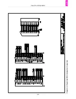
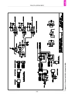
Page 32: ...Panel Card Starterkit 26 Figure 6 1 Panel Card EVB Schematics Bus JTAG ...
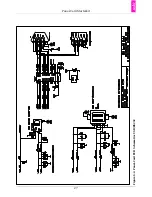
Page 33: ...Panel Card Starterkit 27 Figure 6 2 Panel Card EVB Schematics USB RS232 ...
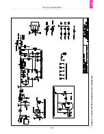
Page 34: ...Panel Card Starterkit 28 Figure 6 3 Panel Card EVB Schematics Power Regulation ...
Page 35: ...Panel Card Starterkit 29 Figure 6 4 Panel Card EVB Schematics Connectors ...
Page 36: ...Panel Card Starterkit 30 Figure 6 5 Panel Card EVB Schematics HID ...
Page 39: ...Panel Card Starterkit 33 Figure 6 8 Panel Card Connector Schematics USB Ethernet ...
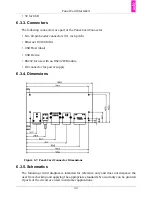
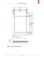
Page 49: ...Panel Card Dimensions 43 Appendix H Panel Card Dimensions Figure H 1 Panel Card 35 Dimensions ...
Page 50: ...Panel Card Dimensions 44 Figure H 2 Panel Card 57 Dimensions ...


