5 – Channel modules : Surround operations
TASCAM DM-4800
User’s Manual
89
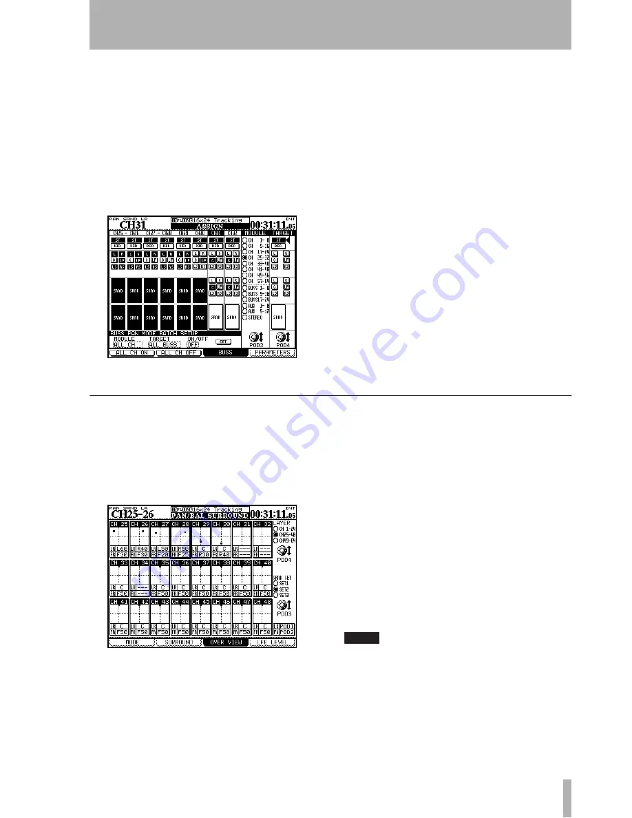
When pan mode is on, the channel settings in the
BUSS ASSIGN
screen look like all the channels in sur-
round set 3 (surround matrix 3) and channels 25
through 30 in surround matrix 2 in Figure 5.26,
Sur-
round assignment
.
When pan mode is off, the channel settings in the
BUSS ASSIGN
screen look like all channels in surround
set 1 (surround matrix 1), and channels 31 and 32 in
surround matrix 2as shown in Figure 5.26,
Surround
assignment
:
The difference between these two modes is that when
pan mode is off, the channels can be assigned indi-
vidually to the surround channels (following Table
5.8,
Buss assignments in surround mode
).
When pan mode is on, the channels can be assigned
to the surround matrices as a whole (either 1, 2 or 3).
•
In both cases, the POD 3 encoder is used to set
the modules displayed on screen (the
SEL
keys
can also be used).
•
The POD 4 encoder is used to select the busses
to which the module is assigned, and the
ENTER
key is used to assign the module, or
release the module from the assignment.
•
The
ASSIGN
indicators also mirror the cur-
rent assignment status, and the
ASSIGN
keys
can also be used to make or break assign-
ments.
Note that when the pan mode is on, all the
ASSIGN
indicators of one buss group (surround matrix) are
turned on with one key.
Surround panning
There are two ways of viewing and setting the pan
position in the surround modes: an overview and a
detailed channel view (the L-R balance can also be
set in the
FADER
screen).
In the overview screen, 24 modules’ basic surround
panning facilities are displayed:
•
Use the POD 3 encoder to select surround
matrix 1, 2 or 3 (
SRND SET
).
•
Use the POD 4 encoder to select the first 24
channel module layer, the second 24 or the
third 16 module layer (
LAYER
).
Using the same assignments as in Figure 5.26,
Sur-
round assignment
, the modules where the pan mode
is off (channels 31 and 32 in matrix 2 in Figure 5.27,
Surround overview
) cannot have any parameters
changed.
However, for channels with the pan mode on (chan-
nels 25 through 30 in matrices 2 and 3 in Figure 5.26,
Surround assignment
), the following controls may be
used:
•
POD 1 moves the channel position (shown as a
dot in the square) around from left to right
(
LR
), and POD 2 moves it from front to rear
(
FR
).
NOTE
In this screen, and the module surround screen, settings
are made independently for each channel, regardless of
the current channel link status.
Figure 5.26: Surround assignment
Figure 5.27: Surround overview


