background image

P r o T r a x   &   M a x T r a x   S a w   T a b l e s

Using the ProTrax Multi-Angle Saw Table: Angle Cutting

7

To set a 6/12 pitch with the  

boom swung to the right, follow  

the previous procedures using  

the markings on the right side of 

the table. 

All other pitches thru 14/12 can 

be cut by following the previous 

procedures and choosing the 

appropriate number and indicating 

lines on the front wear strip.

Commonly cut angles are shown 

as well. Position the appropriate 

work surface at the desired 

position (22 1/2, 30, 45, 60) and  

set up as instructed above.

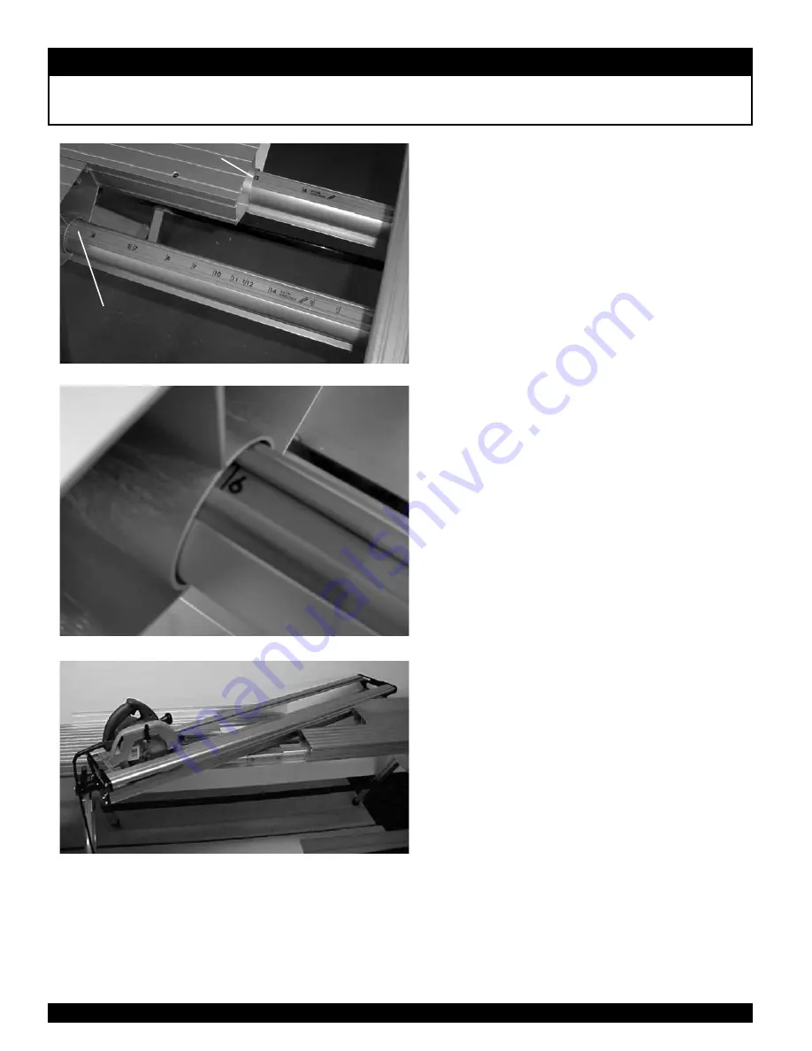
STeP 1 - example of setting 6/12

Slide the work surfaces away from the Boom. The 

markings on the orange wear strip indicate which 

way to rotate the Boom and where to position the 

Work Surfaces. The numbers indicate the pitch. For 

example, “6” indicates a 6/12 pitch, “7” indicates a 

7/12 pitch and so on.

STeP 2 - example of setting 6/12

 Find the “6” indicating line to the left side of the 

Boom on the front wear strip. Slide the left front 

table until it meets the “6”  line. With the right rear 

table pushed out of the way, rotate the handle end 

of the boom leftward until it contacts the work 

surface touching the “6”  line. Lock the Boom by 

rotating the handle to the “up” position. 

STeP 3 - example of setting 6/12 

Slide the remaining Work Surfaces up against the 

boom. Slide the fences into position to support the 

saw tracks. The table is now set for a 6/12 pitch.

SeT 3/12 & 4/12 wITH 

reAr work SUrFACe

SeT 5/12 & 14/12 wITH 

reAr work SUrFACe

Summary of Contents for ProTrax

Page 1: ...tions 1 Setting up your ProTrax 2 Installing the FenceTape 5 Attaching Deck Extender 5 Using the ProTrax 90 Degree Cuts 6 Angle Cutting 7 Cutting a 3 12 Pitch 8 Setting up your MaxTrax 9 Using the Max...

Page 2: ...aluminum alloy sharp edges can occur use caution Transportation When transporting remove the saw and the boom from the table Remove table from the stand Lay the table and the boom flat in bed of truck...

Page 3: ...e Boom can move freely while still attached to the saw table base When the handle is in the up position the Boom is locked The boom must be locked before using the circular saw NOTE The handle is desi...

Page 4: ...ing STEP 6 With the saw tracks in place against the saw base note the position of the alignment marks on the saw tracks and the boom end Match up the marks on the other end of the boom Slide the saw f...

Page 5: ...utton to lock the fence in place To avoid damaging the button don t ram the fence into the button STEP 10 To attach the material stop align the silver nut with the track on the back of the fence and s...

Page 6: ...gure at right STEP 3 Now you can slide the Table Extensions STEP 1 A right hand and left hand tape measure is included Slide the fence tape into the track in the fence until it contacts the saw blade...

Page 7: ...tire width of the Work Surfaces contact the Boom the table is squared and the Boom can be locked Slide the other two Work Surfaces up to the boom STEP 3 After the table is squared you are set up for 9...

Page 8: ...on the orange wear strip indicate which way to rotate the Boom and where to position the Work Surfaces The numbers indicate the pitch For example 6 indicates a 6 12 pitch 7 indicates a 7 12 pitch and...

Page 9: ...3 line With the left front table pushed out of the way rotate the handle end of the boom leftward until it contacts the work surface that is touching the 3 line STEP 2 Push the Boom toward the rear M...

Page 10: ...uctions for the MaxTrax Saw Table are the same as the ProTrax with a few exceptions Page 5 of the ProTrax MaxTrax instructions refer to attaching the optional Deck Extender to saw table The MaxTrax co...

Page 11: ...sing the ProTrax Multi Angle Saw Table Cutting 3 12 Pitch page 8 The MaxTrax has Deck Extenders that need to be against the Boom when cutting Slide the Deck Extenders up to the Boom as shown in the fi...

Page 12: ...sembly or 1 6 turn counter clockwise to loosen the tension Be sure to reinsert the set screw aligned with a flat on the shaft of the Lock Block once the desired setting is achieved Do not tighten the...

Reviews: