CHAPTER 4 DATA SET
28
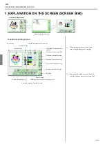
1. EXPLANATION ON THE SCREEN (SCREEN 2000)
<How to call the screen>
Embroidery setting screen
When there is no design data in the memory,
icons of “data edit, needle bar setting, design
data conversion, data set, page switching”
will not be displayed.
Vacant capacity of the memory displays the
number of remaining stitches of design data
that can be registered in the memory.
When the memory has no vacant capacity,
the icons that enable data input of “floppy
disk processing, serial cable connection”
will disappear.
Page switching
Up to 15 designs are displayed at the display
area of memory designs, and 16 and after
designs are displayed at the next page.
16 and after designs are stored at “P2”. Page
switching icons will be added by the number
of designs stored in memory.
It is possible to register up to 99 designs in
the memory.
Design data information
The selected design will be surrounded by a
frame.
Pop-up window
(GC02)
Free Space
Screen 2000
Selecting
Returning to the screen 1000
Floppy disk processing
Serial cable connection
Data edit
Needle bar setting
Design data conversion
Data set
Vacant capacity of memory
Page switching
Display area of memory
Free Space
No.1 - 15
No.16 - 30
No.31 - 45
No.46 - 60
No.61 - 75
No.76 - 90
No.91 - 99
1
CIRCLE
3455st.
Memory No.
Design name
The number of stitches
Select
1
CIRCLE
3455st.
Cancel
Perform data setting
Data Set Ready?
Summary of Contents for TFHX Series
Page 14: ...CHAPTER 2 MACHINE CONSTRUCTION 7 CHAPTER 2 MACHINE CONSTRUC TION GC07...
Page 22: ...CHAPTER 3 OPERATION BASICS 15 CHAPTER 3 OPERATION BASICS GC02...
Page 33: ...CHAPTER 3 OPERATION BASICS 26...
Page 34: ...CHAPTER 4 DATA SET 27 CHAPTER 4 DATA SET GC02 Free Space...
Page 39: ...CHAPTER 4 DATA SET 32...
Page 40: ...CHAPTER 5 EMBROIDERY SETTING 33 CHAPTER 5 EMBROIDERY SETTING GC02 1 2 3 1 2 3...
Page 56: ...CHAPTER 6 DESIGN DATA MANAGEMENT 49 CHAPTER 6 DESIGN DATA MANAGE MENT GC02...
Page 71: ...CHAPTER 6 DESIGN DATA MANAGEMENT 64...
Page 72: ...CHAPTER 7 MANUAL OPERATION 65 CHAPTER 7 MANUAL OPERATION GC03 Xa 43 2 Ya 276 1...
Page 85: ...CHAPTER 7 MANUAL OPERATION 78...
Page 102: ...CHAPTER 9 OUTLINE OF FUNCTIONS 95 CHAPTER 9 OUTLINE OF FUNCTIONS GC02...
Page 108: ...CHAPTER 10 ELECTRO COMPONENT PARTS 101 CHAPTER 10 ELECTRO COMPONENT PARTS GC02...
Page 112: ...CHAPTER 11 TROUBLESHOOTING 105 CHAPTER 11 TROUBLESHOOTING GC02 228...
Page 118: ...CHAPTER 12 MAINTENANCE 111 CHAPTER 12 MAINTENANCE GC02...
Page 124: ...TERMINOLOGY TERMINOLOGY FD11...
Page 131: ...TERMINOLOGY...
Page 132: ...ELECTRO RELATIVE DRAWING ELECTRO RELATIVE DRAWING GC02...
Page 139: ...ELECTRO RELATIVE DRAWING...

