


SKY
-
8
-
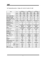
2.3 Technical data table – Models AVR-240, AVR-260, AVR-300
AVR-240 AVR-260 AVR-300
Model 50Hz
R22 R407C R22 R407C R22 R407C
Btu/h 240600 236000 264300 259000 288000 282000
Cooling capacity
Watt 70516 69166 77462 75907 84408 82648
Btu/h 243000 235400 266900 259300 290800 283200
Heating capacity
Watt 71220 69000 78224 76000 85228 83000
Power
Consumption
cooling
Watt 28000 27600 31000 30500 34000 33400
Power
Consumption
Heating
Watt 26600 26000 29400 28800 32200 31600
Operating Current cooling
Amp
47
46.4
50.1
51.2
53.2
56
Operating Current Heating
Amp
44.6
43.6
49.4
48.3
54.2
53
E.E.R-Energy Efficiency Ratio
Cool
8.6
8.5
8.5
8.5
8.47
8.44
C.O.P-Coefficient
Of
Performance
Heat 2.67 2.65 2.66 2.64 2.64 2.62
Moisture Removal
Lit/h
29.2
29.2
30.6
30.6
32
32
Power Supply
Volt/Hz/ph
380/415V, 50Hz, 3ph
380/415V, 50Hz, 3ph
380/415V, 50Hz, 3ph
Condensate Lines - Drain
Ф
- mm (in)
29 (1 1/8")
29 (1 1/8")
29 (1 1/8")
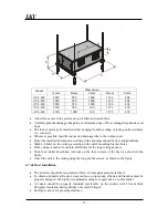
Dimensions (LxDxH)
mm
2630x2000x1870
Net Weight
Kg.
950
Color
RAL 7032
RAL 7032
RAL 7032
Time Delay Fuse
Amp.
3xC63
3xC63
3xC63
Control Mode
I.R. Remote Control / Auto I.R. Remote Control / Auto I.R. Remote Control / Auto
Temperature Control
Microcomputer
Microcomputer
Microcomputer
Evaporator Side
Air Filter
1 Removable/Washable
1 Removable/Washable
1 Removable/Washable
Air Direction Control
Air Ducts
Air Ducts
Air Ducts
m
3
/h 13600
14960
16320
Air Flow (Nominal)
cfm 8000
8800
9600
Net Static Pressure
mm H
2
O 25
25
25
Fan Motor:
HP
4
4
4
Speed (Nominal)
R.P.M
885
765
770
Full Load Amperage
Amp.
6.5
6.5
6.5
Blower Wheel
Type
Centrifugal-Belt Drive
Centrifugal-Belt Drive
Centrifugal-Belt Drive
Condenser Side
m
3
/h 34600
33660
32640
Air flow
cfm 20400
19800
19200
Noise Level
dba
72
72
72
Compressor Thermal Protection
Internal
Overload
Overload
Overload
Full Load Amperage
Amp.
2x22
22+28
2x28
Locked Rotor Amperage
Amp.
2x130
130+150
2x150
Expansion Device
Expansion valve
Expansion valve
Expansion valve
R22 Kg.
10+10
10+11.5
11.5+11.5
Refrigerant Charge
R407C Kg.
9.5+9.5
9.5+11
11+11
R22 Mineral
160P
160P
160P
Oil for Compressor
R407C P.O.E
160ZE
160ZE
160ZE
Outdoor Fan Motor
KW
4x0.66
4x0.66
4x0.66
Speed
R.P.M
900
900
900
Motor Full Load Amperage
Amp.
4x1
4x1
4x1
Summary of Contents for AVL-200
Page 9: ...SKY 9 4 Refrigeration Cycle...
Page 12: ...SKY 12 6 Electrical Wiring Diagram...
Page 13: ...SKY 13...
Page 14: ...SKY 14 NOTES...
Page 22: ...SKY 22 NOTES...
Page 32: ...SKY 32 NOTES...
Page 35: ......
Page 36: ...EN POWER SKY AVL AVR 200 300 V01 R01 JUN 2005...


