


SKY
-
19
-
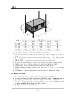
A
C
B
D
E
•
Allow free access to the service door, air filter and control box.
•
Carefully plan the drainage tube path at a minimum slope of 2% avoiding sharp bends or oil
traps.
•
The indoor unit may be installed either hanging from the ceiling or resting on hard surface
(i.e. concrete).
•
Whenever possible, lead the indoor unit drainage tube to the outdoor unit.
•
Select the installation location according to the abovementioned factors and guidelines.
•
Mark 4-6 holes on the ceiling, according to the unit's mounting bracket holes.
•
If the ceiling is made of concrete, drill holes for the long ceiling anchors.
•
Stick four rubber absorbtion cushions on the four corners of the base, as shown in the
figure.
•
Attach the unit to the ceiling using the long anchor screws, as shown in the figure.
6.7 Air Duct Installation
•
The air ducts should be constructed of min. 0.8 mm galvanized metal sheet.
•
To obtain optimal results, dust cross sections, connections, elbows and branches must be
properly designed. We highly recommend seeking for expert advice on this matter.
•
Air ducts should be properly insulated (preferably on the inside) with 50 mm thick
fiberglass insulation having density of at least 24 Kg/m
3
.
•
See figure above for general guidelines.
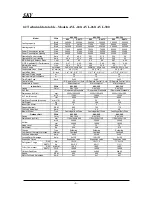
Dimensions
Model
A mm
B mm
C mm
D mm
E mm
AVL-200
2050 800 1000 1326 404
AVL-220
2050 800 1000 1326 404
AVL-240
2050 950 1000 1326 404
AVL-260
2300 950 100 1572 478
AVL-300
2300 1000 100 1572 478
Summary of Contents for AVL-200
Page 9: ...SKY 9 4 Refrigeration Cycle...
Page 12: ...SKY 12 6 Electrical Wiring Diagram...
Page 13: ...SKY 13...
Page 14: ...SKY 14 NOTES...
Page 22: ...SKY 22 NOTES...
Page 32: ...SKY 32 NOTES...
Page 35: ......
Page 36: ...EN POWER SKY AVL AVR 200 300 V01 R01 JUN 2005...


